Chute Design In A Large Coal Handling Facility
David Charles Morgan
T.C.C. (Mech. Eng.) MEMHAcknowledgements : The Bionic Research Institute, Chute Design Conference 1991
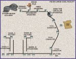
The paper gives a brief overview of coal handling at the Syferfontein Mine, in the Overland Conveyor System, and in the stockyards.
The criteria for selection of chute design are discussed, and design alternatives evaluated.
David Charles Morgan is Projects Manager (Materials Handling) with Keeve Steyn Inc. He is a member of the Institute of Materials Handling, and has wide experience in bulk materials handling and installation.
REQUIREMENT FOR A NEW MINE
Syferfontein Colliery is an entirely new open cast mine situated at Trichardt in the Eastern Transvaal. The purpose of the mine is to supplement the coal supply to Sasol II and Sasol III factories at Secunda and will produce coal in conjunction with four existing mines in the Secunda area.
When fully operational the mine will supply some 7 million tons of coal per annum. This coal will be of a higher grade than that produced from the existing mines and by the mining methods employed, will generate a product with a much lower fines content.
To ensure continuity of product quality to the factories it is necessary to both blend the new mine's coal with that of the existing underground mines and to homogenise the product to ensure an even distribution of fines. The control of the production of fines on the new mine and the transport systems has been of paramount importance and studies conducted by Sasol on the existing systems have been utilised in the design of the transfer points and the design criteria of the conveyors.
MINE OPERATION
Coal is strip mined and transported to the coal preparation plant in trucks with capacities of up to 170 tons. The of mine coal is loaded into a hopper below ground level in the primary crushing building where it is extracted by means of an apron conveyor.
-300mm Material is extracted by means of a live grizzly and transported by conveyor direct to the secondary crushing plant. The +300mm material is transported via a second apron conveyor to a jaw crusher where it is broken down to -300mm and dispatched to the secondary crushing plant.
Prior to secondary crushing the -100mm product is screened out and the crushing by-passed whilst oversize is broken down to the required -100mm by means of a rotary breaker. Rock present in the product at this point is removed by the rotary breaker and discharged by conveyor onto a waste rock pile. The final product now plus fines generated in the mining and reduction process is delivered to a fines screening plant where the desired portion of - 6,4mm product is removed from the final product.
Throughput of the mine is such that the handling system and plant is capable of handling 2400 ton/hour of R.O.M. coal.
A circular stockpile acts as a buffer between the mine and the overland transportation system, from which coal may be extracted at 2000 ton per hour.
To minimise degradation en-route the overland system has been kept to 3 conveyors of which the first is a slow running collection conveyor. Of the other 2 flights, the conveyors have been selected at 8 km and 12 km respectively to keep transfer points to a minimum and belt sag has been restricted to 1% to minimise degradation of the coal en route.
A splitter bin at the factory distributes coal to either the Sasol II or Sasol III stockyards. The new system at Secunda consists of an additional 2 slewing stackers and 2 barrel reclaimers, together with a distribution system to the existing stackers and a reclaim system to the factories.
Despite keeping the transfer points to a minimum a total of 30 individual transfers occur from the R.O.M. intake hopper at the primary crushing building to the stockpiles at Secunda. Careful design of the transfer points to keep degradation to a minimum was therefore quite essential.
Sasol's policy is one of constant improvement and in the process of fixing the conceptual layout many changes occurred both on concept and process requirements. This involved radical changes particularly to the stockyard system from the time of initial conception. This allowed innovative thought to at times complex transfer stations.
CHUTE DESIGN
CONVEYOR CHUTEWORKTo achieve the objectives of Sasol and the necessity to keep degradation to a minimum it was necessary to move away from conventional chutes. Various types of transfer were investigated, catering from in-line dedicated discharge through to multi-discharge and proportioning chutes.
Investigations with Sasol showed that the low headroom curved chute with moving head for multi-discharge was the ideal and enquiries and designs were based on this concept. The specification for the chutes being as follows :
CHUTE SPECIFICATION
The elimination of coal degradation in chutes is of paramount importance and the following are factors influencing the design of degradation free chutes:
A large convex curve of the troughed belt to the head pulley circumference ensuring inherently stable belt and payload with the initial trajectory point lying t 5 out bye of the top dead centre of the head pulley.
Suitably designed belt transition at the head end ensuring a smooth change of payload cross section with minimum surface lump coal movement.
Head pulley of larger diameter than necessary by belt requirements ensuring a more compact trajectory.
The compaction pressure of the coal, determined from its critical superficial moisture level and upper, lower and average size distribution, critical in determining the initial sliding angle of the coal.
Assuring that the coal does not impact on any surface but lands at a low angle of incidence and that free fall is restricted to 500 mm maximum. Preferably coal should slide on the chute for the greatest possible length.
The larger sized coal be cushioned by the fines on landing in the chute.
Discharge of the coal onto the following belt at a near matching speed and inclined at 30 to prevent possible damage to the belt by gouging, cutting or piercing.
All main stream transfer chutes are to consist of the following sections :
A first section tangent to the bottom face of the trajectory, tapering from head chute width to chute discharge width and transforming from a rectangular cross section to a semi-circular section with upper vertical sides and top. The tapering sides to deflect loose lumps back to the main trajectory flow. The length and angle of decline of this section to be determined from coal discharge speed.
A second section of semi-circular cross section with upper vertical sides and top at 30 and 1 m long ensuring that the top of the trajectory meets the coal already sliding in the chute at a very low angle of incidence.
For in-line transfers, the remaining section/s to be as for the second section with angle of decline designed to ensure matching discharge coal and receiving belt speed. The length determined by required height of transfer but to be not less than 1 m.
For angled transfers, the third section to consist of a circular cross .section, the length and angle of decline determined by the angle and height of transfer.
The fourth section for angled transfers to consist of a semi-circular cross section with upper vertical sides and top with a minimum length of 2 m at 30. For a longer section, the last 2 m to be at 30 with the angle of decline of the remainder determined by calculation.
It is required that tests be conducted on the coal to be transported, with the assistance of a neutral body chosen by the contractor and approved by Sasol, before chute designs are finalised.
Chuting shall be manufactured in mild steel. The chuting shall be of the same thickness of metal throughout and be fabricated in lengths with a rigid angle framework at the ends for bolting the chuting together to ensure easy access to pulleys. No section of chuting shall exceed 3 m in length or 3 t in mass, including liners.
Transfer chute design shall be such that the material feed onto the succeeding conveyor is central and in the direction of conveyor travel. All inside surfaces in contact with the conveyed material shall be free from projecting bolts, rivets, high edges, plugs etc.
Starting and stopping of the belt shall be taken into consideration in the design of the chutes and the chutes shall be capable of accepting the overrun of material, without spillage of any material.
The width of the loading chute shall not be greater than 2/3 of the receiving belt measured at the point where the material discharges onto the belt.
Flanges of chutes shall be fully welded along the inside of the chute. Welding along the outside may be staggered except where corrosion can occur.
For ease of maintenance access, the non-material carrying side of the chute shall be removable in panels which can be manhandled. These panels shall be securely bolted to the body of the chute and to each other for the full width of the panel, to provide rigidity and contain dust. Each panel shall be equipped with suitable lifting handles or lugs for ease of handling.
Ceramic tile liners shall be provided wherever wear can occur and these shall be adequately fastened to prevent dislodging under all conditions of material flow. Liners shall be easily replaceable and/or interchangeable where possible. Each tile to be fastened to the chute body or alternatively, every third row to be secured to the chute body.
Joints shall be made to fit exactly to eliminate turbulence in the conveyed material and any inequalities shall be removed. Similarly casings shall not protrude on the inside of chutes.
Dribble chutes receiving fines from the belt cleaners or larger sizes during start-up or stopping and depositing it directly onto the following belt for inline transfer or belt feeder for angled transfer, shall have vertical sides where possible to prevent material build up.
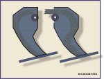
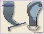
RUN OF MINE FEED CHUTES
VRN 400 liners shall be provided wherever wear can occur, these shall be adequately fastened to prevent dislodging under conditions of material flow. Liners shall be easily replaced and/or interchangeable where possible. The Contractor is to deliver a complete set of steel templates for the manufacture of spare liners, and the cost of such templates is to be included in the tender price. The maximum mass of any one liner shall be 25 kg with a maximum width of 500 mm. Gaps between liners shall not exceed 5 mm.
Joints shall be made to fit exactly to eliminate turbulence in the conveyed material and any burrs or inequalities shall be removed before .or during erection. Similarly bolt or screw or nuts shall not protrude on the inside of chutes.
Dribble chutes receiving fines from the belt cleaners or larger sizes during start-up or stopping and depositing it directly onto the following belt or in-line transfer or belt feeder for angled transfer, shall have vertical sides where possible to prevent material build up.
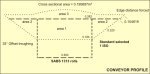
The principle adopted in the in-line transfer on the overland system was that at normal running speeds the coal leaving the head pulley would be projected across an opening and would be caught on a shallow angled sloping face of the chute throat where the coal would slide in a controlled manner onto the next conveyor.
SYFERFONTEIN COLLIERY
TYPICAL OFFSET TRANSFER
NORMAL RUNNING CONDITION
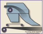
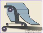
Whilst the main product could be handled comfortably in this manner, scrapings or dribblings had to be caught and transported separately to the next conveyor by means of a collector feeder. During starting and stopping however the coal would be moving too slowly, to safely negotiate the shallow angle of the chute.
In these conditions the trajectory of the coal is insufficient to jump the opening and the coal would fall to the collector feeder below for separate discharge onto the receiving conveyor. This condition would remain until the belt speed had increased to the point where the trajectory would allow passage through the main chute.
SYFERFONTEIN COLLIERY
TYPICAL OFFSET TRANSFER
STARTING AND STOPPING CONDITION
The use of a collector/feeder within the chute does present certain problems in that the starting and stopping philosophy of the conveyors does need to take cognisance of the feeders and the feeders do need to start and stop in a sequence differing from the conveyors themselves, i.e. a delay on the stopping of the feeder must be made to cater for the varying stopping time of .the main conveyors otherwise excessive build up in the chutes will occur.
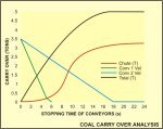
Obviously the chute capacity must be sufficient to cater for stopping due to power failure. Similarly on start up the feeders must be programmed to empty the chute prior to the start of the main conveyor. On the Overland system with such long fast conveyors having extended starting times and long stopping times the carryover during starting and stopping necessitated delayed sequence shutdowns.
Where multi-transfer occurred on the coal preparation plant and stockyard system, the above principle was intended in conjunction with moving heads and twin collecting feeders.
In these cases the feeders played a slightly different role in that they also collected dribblings from the conveyors when the heads were retracted from their forward position.
SYFERFONTEIN COLLIERY
TYPICAL MOVING HEAD
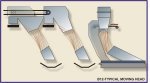
More interestingly a requirement to proportion coal between two discharges with a moving head yet maintain equal distribution of partical size was at one stage requested. This led to the development of a 3 position head wherein its extreme forward and extreme rear position dedicated feeds to either one of the receiving conveyors could be made, where as in the central position the trajectory could be cut vertically and each portion gently caught and guided onto the receiving conveyors.
At a later stage the complexity of the moving heads was a point of concern of SASOL, this led to a decision to revert to the used of conventional chutework with flopper gate route control.
SECUNDA COLLIERS
TWO WAY TRANSFER USING FLOPPER GATES
![]()
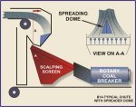
GRIZZLY AND SCREENS
Grizzly and screen underpans were designed to catch the through product and guide it onto the receiving belt. A maximum drop height of 2 metres was the aim in all cases. With screens of 9 metres long x 4,5 metres wide the shaping of the underpan had to be carefully considered to meet the criteria above.
It was also important on the conveyor head chute feeding the screens to generate a spreading of effect upon discharge to ensure even coverage of the screen over its full length and therefore maximise the efficiency of the units.
SYFERFONTEIN COLLIERY
TYPICAL CHUTE WITH SPREADER DOME
CIRCULAR STOCKPILE CHUTES
Particular attention was required on the chutework feeding the circular stockpile stacker boom.
The stacker rotates in a clockwise direction on a continuous basis and the boom luffs and lowers to minimise the impact at discharge onto the stockpile.
The luffing of the boom however affects the feed angle from the chute and rotation of the stacker affects the direction of the material within the chute. All conditions needed to be catered for to ensure central feed onto the boom belt and minimal degradation within the chutework.
SYFERFONTEIN COLLIERY
BOOM FEED
SPLITTER BIN
The splitter bin was designed to run in a low level condition, the capacity being sufficient to prevent stopping of the overland conveyors in the event of nuisance tripping of part of the stockyard system.
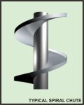
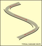
This condition however meant that coals loaded into the top of the bin had to be lowered in a controlled manner to the bottom of the bin to minimise degradation. Two solutions were considered to overcome this, the spiral chute and the cascade chute.
When an internal structure is placed into a bin, which requires free flow of material, certain restrictions occur. Items considered included:
1. The structure submerged in coal.
2. The repose angle of the coal in both the carrying side of the chute and the underside of the chute.
3. The action of the bin whilst filling.
4. The action of the bin whilst emptying.
5. The forces generated by the coal withdrawal.
6. The influence on bin outlets of a moving pile.
7. The ease of removal and repair of the chutework.Whilst the spiral chute offered the best solution for gentle handling of the coal, slow speeds could only be achieved at comparatively shallow angles. The spiral influenced heavily the filling pattern of the bin and exposed itself to severe draw down forces whilst the bin emptied. A model of the action and speed of the coal within the various spirals is currently under development.
The decision was made to utilise a cascade system within the splitter bin. The cascade was of modular construction and compact in design, where the coal was encouraged to move slowly through the transfers from each cascade and the facility was incorporated, that under adverse conditions surplus material could spillover at the affected transfer into the bin. This would occur should the coal fallout of specification or should high fines and high moisture be encountered.
SYFERFONTEIN COLLIERY
TYPICAL SPIRAL CHUTE
SYFERFONTEIN COLLIERY
TYPICAL CASCADE CHUTE
DRUM RECLAIMERS
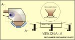
High degradation within the drum reclaimers had been recognised as a problem on the existing units. This problem being primarily caused by the units uprating and the subsequent high belt speeds of the transverse conveyors within the reclaimer body.
Impact, turbulence and subsequent degradation needed to be reduced throughout the new units. This was achieved by increasing the belt with, reducing the belt speed by some 60% and creating a conveyor more similar to a belt feeder with full length skirts, high bed depth and virtually no trajectory from the head pulley. By adopting this approach the rapid change of direction within the drum of coal falling onto the belt was removed, turbulence minimised. At the head station the coal could be turned in the direction of the receiving yard belt instead of impacting directly onto the chute front plate followed by free fall onto a fast moving yard belt.
SECUNDA COLLIERIES
RECLAIMER DISCHARGE CHUTE
CALCULATION OF DEGRADATION
Utilising the. data supplied in a report "Root cause of coal fines at Secunda Collieries" by Mr. D.E. Niemand, based on the coal produced by the existing underground mines and in particular the results of drop tests conducted for that report, KSI developed a computer model to simulate the action of the coal at the transfer points.
Under consideration were the effects of turning the coal by means of a shaped deflector, changing direction by impact onto an angled plate and catching the coal on the underside with a shallow angled plate. Speed and distance travelled in the chute together with partical size plays a major role in determining the effects of collision of the coal with the chutes at the various angles. A paper produced by Prof. A.W. Roberts dealing with the effects of impact and wear of materials on chute liners was examined and the logic modified to consider degradation of the material rather than the chute. This together with data provided in the report above was incorporated into the model. Since ceramic liners are fitted to the chutework it can be considered that the wear on the chute would be negligible.
The model allows criteria to be examined at various vertical drop heights within the chute and calculates the trajectory of the material leaving one plane and its angle of approach to the second plane together with its new velocity. This information allows chutework to be checked and verified at the drawing board.
With specific chute designs complete the model allows selection of specific impact areas and estimates the anticipated degradation of the coal at that point across the particular size range in the ratio of the original sieve analysis. The model examines each particular size individually and after breakage distributes the newly formed smaller particulars across the sieve range.
The results determined at this stage give a revised sieve analysis which may be used for the next transfer or impact point. Sample calculations refer.
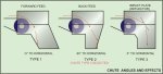
CHUTE ANGLES AND ITS EFFECT ON MATERIAL IMPACT
CHUTE TYPE 2 SELECTED
Input data
| Chute Angle (to Horizontal) | 60 | Friction Angle | 30 |
| Initial Velocity (Horizontal) | 3.42 m/s | CO-EF of Restitution (e) | 0.7 |
| Initial Velocity (Vertical) | 0 m/s | Mean Breakage Energy | 35 |
| Specific Mass of Material | 1.4 T/m | Partical Size | 10 mm |
| Vertical Fall Increment | 0.4m | Partical Mass | 0.0014 kg |
CHUTE ANGLES AND ITS EFFECT ON MATERIAL IMPACT
CHUTE TYPE 2 SELECTED
| Verticle1 Fall (Meters) |
Vertical Velocity (m/s) | Horizontal Velocity (m/s) |
Result Velocity (m/s) |
Angle of Trajectory (Deg) |
Impact Angle (Deg) | Impact Losses Ei/E | Sliding Losses Es/E | Energy Losses E/E | Initial Energy E |
Energy Losses E |
|
|
0 |
0.000 |
3.420 |
3.420 |
0.00 |
-60.00 |
0.5774 |
0.3825 |
-1.5725 |
-1.1900 |
0.008 |
-0.010 |
|
0.4 |
2.801 |
3.420 |
4.421 |
39.32 |
80.68 |
0.1642 |
0.4966 |
0.0134 |
0.5100 |
0.014 |
0.007 |
|
0.8 |
3.962 |
3.420 |
5.234 |
49.20 |
70.80 |
0.3482 |
0.4549 |
0.0551 |
0.5100 |
0.019 |
0.010 |
|
1.2 |
4.852 |
3.420 |
5.936 |
54.82 |
65.18 |
0.4625 |
0.4201 |
0.0899 |
0.5100 |
0.025 |
0.013 |
|
1.6 |
5.603 |
3.420 |
6.564 |
58.60 |
61.40 |
0.5452 |
0.3931 |
0.1169 |
0.5100 |
0.030 |
0.015 |
|
2 |
6.264 |
3.420 |
7.137 |
61.37 |
58.63 |
0.5774 |
0.3718 |
0.1701 |
0.5419 |
0.036 |
0.019 |
|
2.4 |
6.862 |
3.420 |
7.667 |
63.51 |
56.49 |
0.5774 |
0.3546 |
0.2339 |
0.5884 |
0.041 |
0.024 |
|
2.8 |
7.412 |
3.420 |
8.163 |
65.23 |
54.77 |
0.5774 |
0.3403 |
0.2822 |
0.6225 |
0.047 |
0.029 |
|
3.2 |
7.924 |
3.420 |
8.630 |
66.65 |
53.35 |
0.5774 |
0.3282 |
0.3201 |
0.6484 |
0.052 |
0.034 |
|
3.6 |
8.404 |
3.420 |
9.073 |
67.86 |
52.14 |
0.5774 |
0.3179 |
0.3506 |
0.6685 |
0.058 |
0.039 |
|
4 |
8.859 |
3.420 |
9.496 |
68.89 |
51.11 |
0.5774 |
0.3090 |
0.3757 |
0.6846 |
0.063 |
0.043 |
|
4.4 |
9.291 |
3.420 |
9.901 |
69.79 |
50.21 |
0.5774 |
0.3011 |
0.3966 |
0.6977 |
0.069 |
0.048 |
|
4.8 |
9.704 |
3.420 |
10.289 |
70.59 |
49.41 |
0.5774 |
0.2941 |
0.4143 |
0.7084 |
0.074 |
0.053 |
|
5.2 |
10.101 |
3.420 |
10.664 |
71.29 |
48.71 |
0.5774 |
0.2879 |
0.4295 |
0.7174 |
0.080 |
0.057 |
|
5.6 |
10.482 |
3.420 |
11.026 |
71.93 |
48.07 |
0.5774 |
0.2823 |
0.4427 |
0.7250 |
0.085 |
0.062 |
|
6 |
10.850 |
3.420 |
11.376 |
72.50 |
47.50 |
0.5774 |
0.2772 |
0.4542 |
0.7314 |
0.091 |
0.066 |
|
6.4 |
11.206 |
3.420 |
11.716 |
73.03 |
46.97 |
0.5774 |
0.2725 |
0.4644 |
0.7369 |
0.096 |
0.071 |
|
6.8 |
11.551 |
3.420 |
12.046 |
73.51 |
46.49 |
0.5774 |
0.2683 |
0.4734 |
0.7417 |
0.102 |
0.075 |
|
7.2 |
11.885 |
3.420 |
12.368 |
73.95 |
46.05 |
0.5774 |
0.2644 |
0.4815 |
0.7458 |
0.107 |
0.080 |
|
7.6 |
12.211 |
3.420 |
12.681 |
74.35 |
45.65 |
0.5774 |
0.2608 |
0.4887 |
0.7495 |
0.113 |
0.084 |
|
8 |
12.528 |
3.420 |
12.987 |
74.73 |
45.27 |
0.5774 |
0.2574 |
0.4953 |
0.7527 |
0.118 |
0.089 |
CHUTE ANGLES AND ITS EFFECT ON MATERIAL IMPACT
CHUTE TYPE 2 SELECTED
| Vertical1 Fall (Meters) |
100 to 53 | 53.0 to 37.5 | 37.5 to 26.5 | 26.5 to 19.0 | 19.0 to 13.2 | 13.2 to 9.5 | 9.5 to 6.7 | 6.7 to 0.0 | Totals |
|
0 |
0.17% |
0.02% |
0.00% |
0.00% |
0.00% |
0.00% |
0.00% |
0.00% |
0.20% |
|
0.4 |
0.09% |
0.01% |
0.00% |
0.00% |
0.00% |
0.00% |
0.00% |
0.00% |
0.10% |
|
0.8 |
0.17% |
0.02% |
0.00% |
0.00% |
0.00% |
0.00% |
0.00% |
0.00% |
0.20% |
|
1.2 |
0.29% |
0.04% |
0.00% |
0.00% |
0.00% |
0.00% |
0.00% |
0.00% |
0.33% |
|
1.6 |
0.43% |
0.05% |
0.01% |
0.00% |
0.00% |
0.00% |
0.00% |
0.00% |
0.49% |
|
2 |
0.68% |
0.08% |
0.01% |
0.00% |
0.00% |
0.00% |
0.00% |
0.00% |
0.77% |
|
2.4 |
1.06% |
0.13% |
0.02% |
0.00% |
0.00% |
0.00% |
0.00% |
0.00% |
1.21% |
|
2.8 |
1.53% |
0.19% |
0.02% |
0.00% |
0.00% |
0.00% |
0.00% |
0.00% |
1.74% |
|
3.2 |
2.07% |
0.26% |
0.03% |
0.00% |
0.00% |
0.00% |
0.00% |
0.00% |
2.36% |
|
3.6 |
2.69% |
0.34% |
0.04% |
0.01% |
0.00% |
0.00% |
0.00% |
0.00% |
3.07% |
|
4 |
3.38% |
0.42% |
0.05% |
0.01% |
0.00% |
0.00% |
0.00% |
0.00% |
3.86% |
|
4.4 |
4.15% |
0.52% |
0.06% |
0.01% |
0.00% |
0.00% |
0.00% |
0.00% |
4.74% |
|
4.8 |
4.99% |
0.63% |
0.08% |
0.01% |
0.00% |
0.00% |
0.00% |
0.00% |
5.70% |
|
5.2 |
5.90% |
0.74% |
0.09% |
0.01% |
0.00% |
0.00% |
0.00% |
0.00% |
6.75% |
|
5.6 |
6.89% |
0.86% |
0.11% |
0.11% |
0.01% |
0.00% |
0.00% |
0.00% |
7.87% |
|
6 |
7.94% |
1.00% |
0.12% |
0.02% |
0.00% |
0.00% |
0.00% |
0.00% |
9.08% |
|
6.4 |
9.07% |
9.07% |
1.14% |
0.14% |
0.02% |
0.00% |
0.00% |
0.00% |
10.37% |
|
6.8 |
10.27% |
1.29% |
0.16% |
0.02% |
0.00% |
0.00% |
0.00% |
0.00% |
11.74% |
|
7.2 |
11.54% |
1.45% |
0.18% |
0.02% |
0.00% |
0.00% |
0.00% |
0.00% |
13.19% |
|
7.6 |
12.88% |
1.62% |
0.20% |
0.03% |
0.00% |
0.00% |
0.00% |
0.00% |
14.73% |
|
8 |
14.29% |
1.79% |
0.22% |
0.03% |
0.00% |
0.00% |
0.00% |
0.00% |
16.34% |
CHUTE ANGLES AND ITS EFFECT ON MATERIAL IMPACT
CHUTE TYPE 2 SELECTED
VERTICAL 4.8 SELECTED
| Particle Max Min | 100 to 53.0 | 53.0 to 37.5 | 37.5 to 26.5 | 26.5 to 19.0 | 19.0 to 13.2 | 13.2 to 9.5 | 9.5 to 6.7 | 6.7 to 0.0 | Totals |
| INITIAL | 10.20% | 5.60% | 7.30% | 8.80% | 10.30% | 9.00% | 8.90% | 39.90% | 100.0% |
| 53.0 | 6.05% | 0.00% | 0.00% | 0.00% | 0.03% | 0.18% | 0.82% | 3.12% | 10.20% |
| 37.5 | 5.08% | 0.00% | 0.00% | 0.00% | 0.01% | 0.09% | 0.42% | 5.60% | |
| 26.5 | 7.24% | 0.00% | 0.00% | 0.00% | 0.01% | 0.05% | 7.30% | ||
| 19.0 | 8.79% | 0.00% | 0.00% | 0.00% | 0.01% | 8.80% | |||
| 13.2 | 10.30% | 0.00% | 0.00% | 0.00% | 10.30% | ||||
| 9.5 | 9.00% | 0.00% | 0.00% | 9.00% | |||||
| 6.7 | 8.90% | 0.00% | 8.90% | ||||||
| 0.0 | 39.90% | 39.90% | |||||||
| TOTAL | 6.05% | 5.08% | 7.24% | 8.79% | 10.33% | 9.19% | 9.82% | 43.50% | 100.00% |
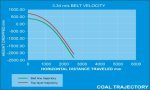
3 ROLL CONVEYOR TRAJECTORY PLOTTING PROGRAMME
| INPUT DATA | OUTPUT DATA | ||
| Belt Velocity | 3.34m/s | Material Depth | 265mm |
| Pulley Diameter | 800mm | Effective rad. on belt line | 420mm |
| Belt Thickness | 20mm | Effective rad. at material top | 585mm |
| Belt Width | 1350mm | Angular velocity (top) | 7.95 rad/s |
| Material Surcharge (ISO) | 18deg | Angular velocity (btm) | 7.95 rad/s |
| Idler Troughing Angle | 35deg | Pulley velocity | 75.94 rpm |
| Incline Angle | 0deg | Tangential velocity (top) | 5.45 m/s |
| Material Density | 0.85 T/m | Tangential velocity (btm) | 3.34 m/s |
| Feed rate (solve for) | 2000 T/h | Angle of contact (top) | 0.00 rad |
| Angle of contact (btm) | 0.00 rad | ||
| VS2 (top) | 1.66 | ||
| VS2 (btm) | 2.71 | ||
| cos of incline angle | 1 | ||
3 ROLL CONVEYOR TRAJECTORY PLOTTING PROGRAMME
| BTM OF MATERIAL | M=0.00 | TOP OF MATERIAL |
M=0.00 |
||||||||
| X1 | D1 | X axis | Y axis | NEW Y axis | X1 | D1 | X axis | Y axis | NEW X axis | NEW Y axis | |
| 0.00 | 420.00 | 684.78 | 0.00 | 684.78 | 0.00 | 684.78 | |||||
| 0.00 | 420.00 | 684.78 | 0.00 | 684.78 | 0.00 | 684.78 | |||||
| 167.00 | 12.26 | 167.00 | 407.74 | 672.52 | 167.00 | 12.26 | 167.00 | 672.52 | 167.00 | 672.52 | |
| 334.00 | 49.05 | 334.00 | 370.95 | 635.73 | 334.00 | 49.05 | 334.00 | 635.73 | 334.00 | 635.73 | |
| 501.00 | 110.36 | 501.00 | 309.64 | 574.42 | 501.00 | 110.36 | 501.00 | 574.42 | 501.00 | 574.42 | |
| 568.00 | 196.20 | 668.00 | 223.80 | 488.58 | 568.00 | 196.20 | 668.00 | 488.58 | 668.00 | 488.58 | |
| 835.00 | 306.56 | 835.00 | 113.44 | 378.22 | 835.00 | 306.56 | 835.00 | 378.22 | 835.00 | 378.22 | |
| 1002.00 | 441.45 | 1002.00 | -21.45 | 243.33 | 1002.00 | 441.45 | 1002.00 | 243.33 | 1002.00 | 243.33 | |
| 1169.00 | 600.86 | 1169.00 | -180.86 | 83.92 | 1169.00 | 600.86 | 1169.00 | 83.92 | 1169.00 | 83.92 | |
| 1336.00 | 784.80 | 1336.00 | -364.80 | -100.02 | 1336.00 | 784.80 | 1336.00 | -100.02 | 1336.00 | -100.02 | |
| 1503.00 | 993.26 | 1503.00 | -573.26 | -308.48 | 1503.00 | 993.26 | 1503.00 | -308.48 | 1503.00 | -308.48 | |
| 1670.00 | 1226.25 | 1670.00 | -806.25 | -541.47 | 1670.00 | 1226.25 | 1670.00 | -541.47 | 1670.00 | -541.47 | |
| 1837.00 | 1483.76 | 1837.00 | -1063.76 | -798.98 | 1837.00 | 1483.76 | 1837.00 | -798.98 | 1837.00 | -798.98 | |
| 2004.00 | 1765.80 | 2004.00 | -1345.80 | -1081.02 | 2004.00 | 1765.80 | 2004.00 | -1081.02 | 2004.00 | -1081.02 | |
| 2171.00 | 2072.36 | 2171.00 | -1652.36 | -1387.58 | 2171.00 | 2072.36 | 2171.00 | -1387.58 | 2171.00 | -1387.58 | |
| 2338.00 | 2403.45 | 2338.00 | -1983.45 | -1718.67 | 2338.00 | 2403.45 | 2338.00 | -1718.67 | 2338.00 | -1718.67 | |
| 2505.00 | 2759.06 | 2505.00 | -2339.06 | -2074.28 | 2505.00 | 2759.06 | 2505.00 | -2074.28 | 2505.00 | -2074.28 | |
AREAS OF IMPORTANCE
MATERIAL CARRYOVER
Within the Syferfontein system the size of the conveyors and stopping times of the respective conveyors gives cause for concern of other areas. Two particular instances are as follows :
The 12 km overland conveyor fed onto a 1 km inclined conveyor, at which point the transfer was able to contain the carryover of coal due to the varying stopping times, however the discharge from the chute at start up was quite capable of flooding the receiving belt beyond the point of spillage. Control of the outflow of the chute was therefore necessary. By restricting the flow to 2500 ton/hr an acceptable local overload slug of some 35 metres could be handled without spillage or detriment to the system.
The above is not always the case and a particular example occurred within the stockyard distribution wherein a 2 km slightly declined conveyor was required to feed onto a 100 metre inclined conveyor. The inclined conveyor was one of a chain of similar conveyors feeding the stacking systems.
The carryover generated if left to its own devices would flood the 110 metre conveyor causing spillage. More importantly the carryover was quite capable of generating a slug of material in excess of the length of the existing stacker boom lengths causing major overload of these conveyors. Here a vicious circle can easily be generated since a trip of the stacker boom on overload would generate a second slug at the transfer of the 2 km conveyor to the 100 metre conveyor thus priming the system upon start up for another boom belt trip. Control of the outlet of the chute together with considerable braking of the 2 km conveyor was therefore necessary to give an acceptable situation.
From the above it can be seen that it is insufficient to assume that carryover may be simply contained within a chute without consideration of the effects on the entire system.
At KSI models were created to monitor the flow of coal through the chutes under the various stopping conditions. These models allow for restricted flow onto the conveyors without creation of a spillage and totalise the surplus coal retained in the chutes. The following examples show the monitoring of the material at the discharge between two conveyors and the build up of coal that occurs within the chute during stopping. The model may be adjusted to cater for the various stopping conditions of the two conveyors and the allowable overload of the receiving conveyor.
As the conveyors stop the quantity of material on the receiving conveyor increases until it reaches a prescribed limit. From that point the surplus material is held inside the chute where it will be discharged on start-up, also at the prescribed limit of the conveyor capacity.
The model may also be run to consider the build up occurring within the chutes with the material at different bulk densities, since the chute opening will control the material on a volume basis not a ton/hour rate.
It follows that a number of such examples need to be considered at any transfer point where a danger exists in the feeding conveyor stopping in a longer time than the receiving conveyor. The most common case occurs in the discharge between along yard belt and a stacker boom conveyor.
As mentioned earlier the slug of material generated under such stopping conditions also needs consideration. The following examples show the slugs effect on the receiving conveyor and any other small conveyor downstream of the discharge.
STANDARD SELECTED 1 ISO
STANDARDS AVAILABLE 1 ISO
2 CEMA
3 DIN
4 BS 2890Data
Material depth 0.265 m Offset (0) in line (1) 0 type Belt width 1.350m Troughing angle 35 deg Edge dist 0.092 m Edge dist (forced) 0.105 m Surcharge angle (ISO) 18 deg Surcharge angle (DIN) 12.00 deg Material width 1.025 m Cross sec. area 0.196 m2 Calc. belt width 1.350 m Belt speed 3.34 m/s Material density 0.85 t/m Incline angle 5 deg Incline factor 1 Belt capacity 2000 t/h Areas
radius 1.658 m area1 0.092 m2 area2 0.048 m2 area3 0.056 m2 total 0.196 m2
Standard edge distance 0.0925 m 3 - ROLL BELT CAPACITY AND EDGE CLEARANCE PROGRAMME
CROSS SECTIONAL AREA = 0.195687 m2
MATERIAL ACCUMULATION AT TRANSFER POINT DURING EMERGENCY STOPPING
|
CONDITION : Emergency stop of conveyor CON 2 in the INCLINES Loaded condition |
| Conveyor CON 1 details | Conveyor CON 2 details | Calculated stopping condition | ||||||
| Max. cap belt | 2000 t/hr | Max. cap belt | 2400 t/hr | Total mat'l discharged from conveyor no. CON 1 | 5.88 5.00 |
m Tons |
||
| Opp. tonnage | 2000 t/hr | Opp. tonnage | 2000 t/hr | |||||
| Belt width | 1200 mm | Belt width | 1350 mm | Total mat'l extracted from chute | 2.06 1.75 |
m Tons |
||
| Conv. length | 2500 m | Conv. length | 100 m | |||||
| Conv. lift | -3.0 m | Conv. lift | 5.0 m | Total mat'l held in chute | 3.82 3.25 |
m Tons |
||
| Belt velocity | 3.42 m/s | Belt velocity | 3.42 m/s | |||||
| Mat'l density | 0.85 t/m | Mat'l density | 0.85 t/m | Total additional mat'l to be handled by conveyor no. CON 2 | 5.88 5.00 |
m Tons |
||
| Decelaration | 0.190 m/s2 | Decelaration | 0.650 m/s2 | |||||
| Acceleration | 0 m/s2 | Acceleration | 0 m/s2 | Total capacity of chute | 8.00 6.80 |
m Tons |
||
| STOPPING TIME 18.00 sec | STOPPING TIME 5.26 sec | |||||||
MATERIAL ACCUMULATION AT TRANSFER POINT DURING EMERGENCY STOPPING
|
CONDITION : Emergency stop of conveyor CON 2 in the INCLINES Loaded condition |
|
TIME s |
BELT VEL m/s |
TRAVEL DISTANCE m |
DEL'Y RATE t/s |
DISCHARGE CUMULATIVE Tons |
BELT VEL m/s |
TRAVEL DISTANCE m |
EXTRACTION RATE t/s |
EXTRACTION CUMULATIVE Tons |
MATERIAL CARRY OVER | |||
| Tons | m | |||||||||||
|
0 |
3.42 |
0.00 |
0.00 |
0.00 |
3.42 |
0.00 |
0.00 |
0.00 |
0.00 |
0.00 |
||
|
1 |
3.23 |
3.32 |
0.54 |
0.54 |
2.77 |
3.09 |
0.54 |
0.54 |
0.00 |
0.00 |
||
|
2 |
3.04 |
6.46 |
0.51 |
1.05 |
2.12 |
5.54 |
0.51 |
1.05 |
0.00 |
0.00 |
||
|
3 |
2.85 |
9.40 |
0.48 |
1.53 |
1.47 |
7.34 |
0.38 |
1.43 |
0.10 |
0.12 |
||
|
4 |
2.66 |
12.16 |
0.45 |
1.98 |
0.82 |
8.48 |
0.22 |
1.65 |
0.32 |
0.38 |
||
|
5 |
2.47 |
14.73 |
0.42 |
2.39 |
0.17 |
8.98 |
0.10 |
1.75 |
0.64 |
0.76 |
||
|
6 |
2.28 |
17.10 |
0.39 |
2.78 |
0.00 |
9.00 |
0.00 |
1.75 |
1.02 |
1.20 |
||
|
7 |
2.09 |
19.29 |
0.35 |
3.13 |
0.00 |
9.00 |
0.00 |
1.75 |
1.38 |
1.62 |
||
|
8 |
1.90 |
21.28 |
0.32 |
3.46 |
0.00 |
9.00 |
0.00 |
1.75 |
1.70 |
2.00 |
||
|
9 |
1.71 |
23.09 |
0.29 |
3.75 |
0.00 |
9.00 |
0.00 |
1.75 |
2.00 |
2.35 |
||
|
10 |
1.52 |
24.70 |
0.26 |
4.01 |
0.00 |
9.00 |
0.00 |
1.75 |
2.26 |
2.66 |
||
|
11 |
1.33 |
26.13 |
0.23 |
4.24 |
0.00 |
9.00 |
0.00 |
1.75 |
2.49 |
2.93 |
||
|
12 |
1.14 |
27.36 |
0.20 |
4.44 |
0.00 |
9.00 |
0.00 |
1.75 |
2.69 |
3.17 |
||
|
13 |
0.95 |
28.41 |
0.17 |
4.61 |
0.00 |
9.00 |
0.00 |
1.75 |
2.86 |
3.37 |
||
|
14 |
0.76 |
29.26 |
0.14 |
4.75 |
0.00 |
9.00 |
0.00 |
1.75 |
3.00 |
3.53 |
||
|
15 |
0.57 |
29.93 |
0.11 |
4.86 |
0.00 |
9.00 |
0.00 |
1.75 |
3.11 |
3.66 |
||
|
16 |
0.38 |
30.40 |
0.08 |
4.94 |
0.00 |
9.00 |
0.00 |
1.75 |
3.18 |
3.75 |
||
|
17 |
0.19 |
30.69 |
0.05 |
4.98 |
0.00 |
9.00 |
0.00 |
1.75 |
3.23 |
3.80 |
||
|
18 |
0.00 |
30.78 |
0.02 |
5.00 |
0.00 |
9.00 |
0.00 |
1.75 |
3.25 |
3.82 |
||
|
19 |
0.00 |
30.78 |
0.00 |
5.00 |
0.00 |
9.00 |
0.00 |
1.75 |
3.25 |
3.82 |
||
|
20 |
0.00 |
30.78 |
0.00 |
5.00 |
0.00 |
9.00 |
0.00 |
1.75 |
3.25 |
3.82 |
||
|
21 |
0.00 |
30.78 |
0.00 |
5.00 |
0.00 |
9.00 |
0.00 |
1.75 |
3.25 |
3.82 |
||
|
22 |
0.00 |
30.78 |
0.00 |
5.00 |
0.00 |
9.00 |
0.00 |
1.75 |
3.25 |
3.82 |
||
|
23 |
0.00 |
30.78 |
0.00 |
5.00 |
0.00 |
9.00 |
0.00 |
1.75 |
3.25 |
3.82 |
||
|
24 |
0.00 |
30.78 |
0.00 |
5.00 |
0.00 |
9.00 |
0.00 |
1.75 |
3.25 |
3.82 |
||
The example shows that such a slug has little or no effect when discharged onto a long conveyor. The conveyor simply does not see the slug since its mass is insignificant to the mass already on the conveyor. Further an empty portion of belt will follow the slug since this type of slug will only be seen on start up. It is quite a different story however when the slug is discharged onto a small conveyor. Here the conveyor may become grossly overloaded even whilst the plant is running below its maximum capacity. It may not be clear to the operating staff why a short conveyor persistently trips at a reduced tonnage. The conveyor must be designed in such a manner that tripping under such conditions does not occur and the carryover during stopping at a transfer point which includes such a conveyor downsteam must be kept to an absolute minimum.
PORTION OF BELT OVERLOADED BY CARRY OVER DURING STOPPING
Material carried over . 5 Tons (From "Carryo") (Incl. Mat.not held in chute)
| Conveyor capacities | RECEIVING CONVEYOR | SHORTEST CONVEYOR |
| Maximum cap. of belt | 0.280 m/s2 | 0.348 m/s2(At the point of spill) |
| Restricted cap. of belt | 0.247 m/s2 | 0.247 m/s2 (Baffle or chute opening) |
| Selection (max = 0, rest =1) | 0 | 0 |
| Selected capacity | 0.247 m/s2 | 0.247 m/s2 |
| RECEIVING CONVEYOR | FEED LENGTH (m) |
FEED RATE (t/h) |
BELT SPEED (m/s) |
MATERIAL DENSITY (t/m) |
CROSS SEC. AREA (m2) |
TOTAL MATERIAL (Tons) |
| NORMAL | 76.18 | 1800 | 3.34 | 0.85 | 0.1761 | 11.40 |
| O/LOAD | 23.82 | 2524 | 3.34 | 0.85 | 0.2470 | 5.00 |
| TOTAL | 100.00 | 1973 | 3.34 | 0.85 | N/A | 16.40 |
The conveyor has therefore a minimum power requirement based on . 1973 tons/hour.
And a minimum tension (sag) based on 2524 tons/hour.
| SHORTEST CONVEYOR | FEED LENGTH (m) |
FEED RATE (t/h) |
BELT SPEED (m/s) |
MATERIAL DENSITY (t/m) |
CROSS SEC. AREA (m2) |
TOTAL MATERIAL (Tons) |
| NORMAL | -3.82 | 1800 | 3.34 | 0.85 | 0.1761 | -0.55 |
| O/LOAD | 23.82 | 2600 | 3.34 | 0.85 | 0.2470 | 5.00 |
| TOTAL | 20.00 | 2600 | 3.34 | 0.85 | N/A | 4.2 |
The conveyor has therefore a minimum power requirement based on . 2600 tons/hour.
And a minimum tension (sag) based on 2600 tons/hour.
N.B.!! The tons per hour calculated excludes in incline factor.
PORTION OF BELT OVERLOADED BY CARRY OVER DURING STOPPING
Material carried over . 5 Tons (From "Carryo") (Incl. Mat.not held in chute)
| Conveyor capacities | RECEIVING CONVEYOR | SHORTEST CONVEYOR |
| Maximum cap. of belt | 0.280 m/s2 | 0.348 m/s2(At the point of spill) |
| Restricted cap. of belt | 0.247 m/s2 | 0.247 m/s2 (Baffle or chute opening) |
| Selection (max = 0, rest =1) | 0 | 0 |
| Selected capacity | 0.247 m/s2 | 0.247 m/s2 |
| RECEIVING CONVEYOR | FEED LENGTH (m) |
FEED RATE (t/h) |
BELT SPEED (m/s) |
MATERIAL DENSITY (t/m) |
CROSS SEC. AREA (m2) |
TOTAL MATERIAL (Tons) |
| NORMAL | 76.18 | 1800 | 3.34 | 0.85 | 0.1761 | 11.40 |
| O/LOAD | 23.82 | 2524 | 3.34 | 0.85 | 0.2470 | 5.00 |
| TOTAL | 100.00 | 1973 | 3.34 | 0.85 | N/A | 16.40 |
The conveyor has therefore a minimum power requirement based on . 1812 tons/hour.
And a minimum tension (sag) based on 2524 tons/hour.
| SHORTEST CONVEYOR | FEED LENGTH (m) |
FEED RATE (t/h) |
BELT SPEED (m/s) |
MATERIAL DENSITY (t/m) |
CROSS SEC. AREA (m2) |
TOTAL MATERIAL (Tons) |
| NORMAL | -3.82 | 1800 | 3.34 | 0.85 | 0.1761 | -0.55 |
| O/LOAD | 23.82 | 2600 | 3.34 | 0.85 | 0.2470 | 5.00 |
| TOTAL | 20.00 | 2600 | 3.34 | 0.85 | N/A | 4.2 |
The conveyor has therefore a minimum power requirement based on . 1835 tons/hour.
And a minimum tension (sag) based on 2524 tons/hour.
N.B.!! The tons per hour calculated excludes in incline factor.
REFERENCES AND ACKNOWLEDGEMENTS
The concepts, specifications and final approvals of the coal preparation plant were undertaken in conjunction with Syferfontein Project Team.
The final concepts, specifications and final approval for the Coal Stockyard were undertaken in conjunction with Secunda Project Management Services.
Coal Preparation Plant: Constructed by Osborn M.M.D.
Overland Conveying System: Constructed by Krupp SA
Coal Stockyard: Constructed by Koch SA
Coal Degradation basis: Report by Mr D.E. Niemand (Sastech)
Curved Chute Concepts: L. Barnish & Associates
Impact of coal on chutes: Based on Prof. A.W. Roberts
Final Chute design: Messrs. Osborn M.M.D, Krupp SA, Koch SA
![]()