Belt Rip Control In Underground Chutes
Terry KG Hein B.Sc (Mech Eng) B Comm
Acknowledgements : The Bionic Research Institute, Chute Design Conference 1991
Belt rip control caused by Tramp material is an ever present operating hazard in underground conveying. This paper reviews typical mining methods, conveyor belt selection, and chute design to limit ripping.
Terry Hein is Consulting Mechanical Engineer (Underground Collieries) at Rand Mines (Mining and Services) Ltd.
He has wide experience on mines -opencast and underground -handling Phosphate, Copper, Manganese, Coal, and Chrome.
SYNOPSIS
Underground collieries are a large consumer of conveyor belting. The transport distances are extensive on developed mines with many transfer points along the coal route. It is at these transfer points that belt ripping, tearing and wear takes place:
Various modes of belt degradation are reviewed and some chute designs are recommended to control belt ripping.
1. INTRODUCTION
Conveyors are the main mode of materials handling in collieries. The conveyor system is extensive with many transfer points.
The chrome mines have a single series of incline conveyors transporting the material to surface. Rates of mining are not very fast re 30-50000 TP. month but due to the chrome seams outcropping on surface it has been simple to follow the declining chrome seam with a conveyor installation. A few transfer chutes are used, these being at the working levels.
The Chamber of Mines Annual Review indicates that R70m was spent on conveyor belting on the Chamber collieries in 1990.
There is no record of the amount that is spent on replacement belting but an estimate by the Rand Mines group indicates that this could be v some 50 to 60% of annual consumption. It must not be forgotten that PVC belting is mainly used underground and this has a limited life of around three years.
The record of belt rip on underground conveyors is not well recorded but that for some surface overland systems the extent of belt rip has been catastrophic; lengths of some 3000m have been ripped. The surface conveyor systems are extremely long and use steelcord conveyor belting whilst those underground are limited to flights of 2000m. On one underground colliery a booster drive conveyor of 5000m has now been installed. This installation uses PVC belting and clipped joints.
Due to the underground collieries being the main consumers of conveyor belting the paper will be contained to chutes in collieries.
2 . TYPICAL COLLIERY LAYOUT AND MINING SYSTEMS
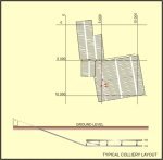
A typical layout of an underground colliery producing one million tons of coal per month for a power station is shown in Figure 1. This particular mine operates on two seams, the figure showing in plan only one seam superimposed on the seam below.
Fig 1: Typical colliery layout
The coal is brought to surface by a twin steelcord conveyor system in a single incline shaft.
In the mine shown, coal is mined by continuous miners leaving suitable pillars to support the roof. Mining takes place in sections, some 100 metre wide by 900 metre long.
Coal is broken from the coal face by the continuous miners and loaded into shuttle cars which transfer their load into a feeder breaker which controls the feed rate, whilst crushing, onto the section conveyors. The section conveyors are advanced on a daily basis as the coal face advances to reduce the tramming distance of the shuttle cars.
The section conveyors transfer the coal via a chute onto a trunk conveyor which feeds a bunker. Coal from the bunker is fed by vibrating feeders onto two horizontal spine conveyors which feed into a bunker from which the coal is fed to the incline conveyors.
To achieve the total output of one million tons per month at least 23 sections will be needed. The total conveyor belting requirement for the colliery is shown in Table 1.
| CONVEYOR | No | WIDTH mm |
CAPACITY T.P.H. |
SPEED m/s |
TOTAL LENGTH m |
TYPE | CLASS | INVESTMENT R (000) |
| SECTION | 46 | 1050 | 400 - 800 | 2.5 | 36000 | PVC | 800 | 5760 |
| TRUNK | 20 | 1350 | 1600 - 2000 | 3.0 | 60000 | PVC | 1250 | 12000 |
| MAIN SPINE | 10 | 1500 | 2400 - 2800 | 3.5 | 35000 | FABRIC | 800 | 10500 |
| INCLINE | 2 | 1500 | 3500 | 4.2 | 2400 | STEELCORD | 2600 | 12000 |
The total investment in conveyor belting is R40m out of a total investment of R700m.
There will be approximately 94 transfer points. Each one of these transfer points being a potential belt ripping point.
The total loss of any conveyor belt would be limited to its full length which for section conveyors amounts to R352 000 (2200m) and the incline conveyor R600 000 (1200m).
It is envisaged that belt rip would be detected or the belt stopped well before the full belt length is torn but the extent of the cost including downtime, repair work and recovery of spillage could be quite substantial.
3. QUALITY OF LOADING MATERIAL ONTO THE CONVEYOR SYSTEM
The size, type and grading of the material being fed onto a conveyor system is very dependent on the control at the mining face.
The geology of the coal seam is not always predictable and layers of stone or floating stones may be found in the seam. These stones from the seam, or, stones from collapsing roof are often loaded directly onto a conveyor system although in a well managed and controlled environment this material is usually crushed in a feeder breaker before entering the belt system.
Belt ripping can be reduced by ensuring that material is sized correctly before being placed on the conveyor system.
Often where continuous miners are used operators consider that the material is adequately sized due to the number of picks on the drum breaking the coal and do not utilise a breaker before the section conveyor only to find that extremely large slabs are loaded which need to be manhandled off the conveyor.
Other deleterious material such as wooden poles and roof bolts are added to the coal stream by persons cleaning up the area. These long objects are difficult to handle in a chute and inevitably cause a blockage or cutting of the conveyor belt.
4. FAILURE MODES OF CONVEYOR BELTS
Failure of conveyor belting occurs due to general wear of the covers, fatigue of the carcass or by ripping and tearing.
Ripping and tearing in many cases can be patched temporarily but where it is extensive, belt replacement usually occurs.
Chutes can be designed which reduce the effect of belt deterioration. The modes of deterioration of conveyor belts being-
- Slow abrasive wear.
- Gouging -usually caused by material stuck against chutes.
- Puncturing of carcass and cover large material or sharp objects falling from a height. Large material jammed between belt and pulley.
- Side tearing belt alignment problems, poor centering of load and narrow chutes.
- Ripping or splitting belt pierced by an object which is then jammed and belt cut in two.
5. CHUTE DESIGN FOR RIP CONTROL
5.1 Belt Splitting
Belt splitting occurs when the conveyor belt is pierced by a sharp object such as a roof bolt, steel liner or sharp rock which has been jammed in the chute itself or has wedged against an idler, the conveyor belt being cut whilst it continues travelling.
A roof bolt or steel spike flowing with the coal from a feed conveyor would need to fall from a reasonable height to pierce the conveyor. To reduce this effect transfer heights should be reduced or else a sliding chute should be introduced to contain the flow as it comes off the feed head pulley and direct the material in the direction of the receiving conveyor.
Figure 2 shows a typical loading chute at the coal face and a modified chute with sliding plate chute to reduce the effect of piercing of the belt by steelrods.
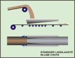
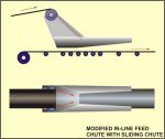
Fig 2: Typical in line feed and transfer chute
It is common practice to design loading chutes with a "langlaagte", type of opening so that centering of the material takes place on the conveyor. If this opening at the feed end is smaller than some of the material being fed in, then blockages can occur causing the material to rub on the conveyor belt. Sharp rocks would then cut the conveyor.
It is therefore important that the opening on the control chute is adequately sized for the largest lump size expected. The designer cannot take cognizance of the large material which may be thrown onto the belt during cleanup. Discipline of the operating personnel is important.
Figure 3 shows a typical chute used at the transfer point of a section conveyor onto a trunk conveyor.
![]()
Fig 3: Typical transfer chute - section to trunk conveyor
This chute is very simple and is used extensively in the collieries. It requires very little maintenance and centering of the coal on the receiving conveyor is simply carried out by movement of the impact plates. No skirt plates are used and there is no restriction to coal passing through the transfer point. The drop is usually some 1 to I metres and is very much dependant on the seam height.
There is always the possibility that the belt can be pierced by a sharp object and the belt ripped on this type of transfer point. On high speed receiving belts the conveyor belt has to change the material direction and much spillage occurs.
A proposed chute design such as in Figure 4 is recommended.
In the modified chute design the material off the section conveyor is collected on a circular shaped impact trough and the material then forced by the slope of the trough in the direction of the receiving conveyors. The trough is shown hanging from chains so that the position can be altered and turned to give the best transfer position.
This chute has been successfully used on some mines and has eliminated a lot of spillage, whilst reducing the wear on the receiving conveyor.
Conveyor belt ripping is reduced as the material fall is reduced and the flow is in the direction of the receiving belt.
A more sophisticated version of the troughed chute could be incorporated which picks up the material at the section conveyor head chute and turns the flow onto the receiving belt. To do this, greater headroom is required.
Liner plates are a common cause of belt rip. The usual problem being that they have sharp edges and that they are fairly long and can be jammed in a chute. It is recommended that when steel liners are used they should be limited in size and always bolted in. If possible, other lining material such as ceramic tiles or rubber should be used. Belt ripping by liner plates is generally aggravated by poor maintenance of the chutes.
5.2 Puncturing
Puncturing of a conveyor belt will occur when a sharp object pierces the belt and is pushed out again or by a heavy blunt object " that due to the energy of its fall tears the belt carcass. This generally does not result in any downtime of the system but reduces the life of the belt carcass. Patching of the tear can be repaired during maintenance periods.
Belting with inadequate number of plies and steelcord belts are more susceptible to this failure. Solid woven conveyor belts have greater resistance to this type of failure.
To eliminate this type of failure, high transfer heights must be avoided and material flow directed in the direction of the receiving belt. This can be accomplished by the use of a sliding chute such as in Figures 2 and 4.
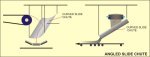
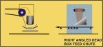
Fig 4: Modified transfer chutes - section to trunk
5.3 Gouging
Gouging of a conveyor belt is defined as the tearing of the covers longitudinally by a blunt object. This usually occurs when material is allowed to jam in or against the chute causing a high pressure to be exerted on the surface of the belt. This gouging can occur on the top or bottom surface.
To alleviate gouging, adequate clearance is required between conveyor belt and chute; especially, in systems where a number of transfer points exist on the same conveyor. Chutes should also be made large enough to accommodate maximum flow rates and eliminate blockages.
In general this does not occur underground too often as conveyor belt widths are more than adequate to take the flow rates and similarly chutes are large and open. No rubber skirts are used.
5.4 Side Tearing
Side tearing of conveyor belts is caused by the continuous rubbing of the side of the belt against a sharp object which can be a chute, guard or vertical support member.
Side tearing is usually a slow process but is aggravated where clipped joints are used on conveyors.
The cause of belt misalignment is poor installation. of conveyor structure, poor maintenance of idlers, poor conveyor belt manufacture or the poor centering of coal flow at the transverse points causing the belt to track to one side.
Section conveyors which require a rapid advance and are temporary installations are especially susceptible to side tearing.
The section loading chute as shown in Figure 2 shows the typical "langlaagte" chute with a throat enlarging from the feed point to the discharge end.
Fig 2: Typical in line feed and transfer chute
This chute assists with centering of the flow onto the conveyor even in cases where the feeder is off centre. This type of chute is recommended at all in-line feed points. The troughed half round sloping chute is very similar.
Chute widths should allow adequate clearance for the misaligned belt to wander. On some mines it is standard practice to have pulley face widths 150mm greater than the belt width and then a further clearance of 5Omm between pulley end and chute as shown in Figure 5.
![]()
Fig 5: Chute clearance to belt width
These large clearances limit the occurrence of the belt edge contacting the chute side and also reduces the chance of the belt folding back on itself.
6 . CHUTE LIMITATIONS
Chutes are generally designed to cater for a limited material size and therefore cannot be expected to cope with large tramp which is sometimes thrown on conveyor belts such as: wooden props, roof bolts and large falls of hanging which usually contain flat stones.
Wooden props and roof bolts which are no less than 1,2m in length are difficult to turn in chutes and therefore should be eliminated by proper operation.
7. OTHER MEANS OF REDUCING BELT RIP
Proper maintenance of idler in the chute area is required especially as there is usually some spillage. Idlers should not be allowed to wear through or to be removed from their frames and the belt run over brackets.
It is possible that idlers are "sprung" from their brackets by heavy objects falling on the conveyor belt. Reduction of transfer height should be incorporated by suitable sliding chutes.
Where impact idlers are a maintenance problem sliding impact beds are beneficial. These impact beds (Figure 6) have a metal or U.H.M.W.P.E. surface with rubber backing to give some spring so that belt carcass is not damaged.
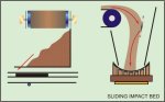
Fig 6: Sliding impact bed
These impact beds help to reduce through piercing of the belt and consequent ripping as the object is resisted by the surface plate.
Where ripping of high cost conveyor belts such as incline shaft conveyors can occur it is usual to reduce tramp steel by removal on an accelerator conveyor with a magnet or detection by a metal detector.
Further rip can be controlled on a conveyor belt by means of monitoring coils installed in the belt which will allow a detector to stop the drive as soon as a broken coil is detected.
8 . CONCLUSION
Belt rip can be reduced by chute design. The elimination of belt rip is dependant on the control of the total system environment. Effective maintenance management and operational controls are necessary to eliminate objects on conveyor belts that the system has not been designed for.
Other control and detection systems are available which will also reduce belt rip.
The most important aspects in reducing rip are:-
- Reduced transfer height.
- Material flow from chute to be in direction of receiving belt.
- Centering of load.
- Clearance between bottom of chute and belt.
- Adequate clearance between bottom of chute and belt.
- Maintenance of chutes.
- Liners smaller than chute outlets.
![]()