Degradation Control In Transfer Chutes
C.L. SNOW
L. S. BARNISH & PARTNERSAcknowledgements : The Bionic Research Institute, Chute Design Conference 1991
Coal conveyor networks have pertinent characteristics which affect the magnitude of degradation. This paper reviews the problems and indicates appropriate solutions to reduce degradation.
Chris Snow is the Managing Partner of Barnish and Partners, Consulting Engineers. He has been involved in bulk materials handling since 1980, when as Research Officer at the University of the Witwatersrand. He studied problems of backfill in deep gold mines. He was Senior Design Engineer with Spencer (Melksham), SA (Pty) Ltd, and Drewett, Hubble & Pokory Inc, before joining Barnish and Partners.
SYNOPSIS
This paper addresses some of the issues of minimising degradation of material within a transfer chute.
It covers the practical aspect of reducing the amount of energy change associated with the material being transferred.
The paper discusses some methods of reducing the degradation by analysing the trajectory, and by examining the feed conveyor characteristics.
1. INTRODUCTION
1.1 Today's demands on raw materials, and the ever present cost increases associated with the process of raw materials place a heavy penalty on waste and squander.
1.2 Most often there are large distances between raw material and user.
1.3 Thus the tremendous effort (and cost) of recovery of raw materials must be complimented by a suitable transport system. This system should not devalue the product being transported, but at least retain the product as close to original as possible.
1.4 One of the most significant "devaluing" elements that occurs is DEGRADATION. This is the disintegration of material by wear and impact.
1.5 Degradation produces undesired and at times unusable by-products that are discarded as waste. This discard decreases the yield of that particular material and increases the cost. Further it requires that some form of separation be conducted, again giving rise to cost.
1.6 If we were to reduce the amount of degradation involved in transport of materials, the effective yield of usable product will rise, and so reduce costs in having to separate and treat.
1.7 The majority of raw material transport systems involve conveyors. These are linked together to form the desired routing. Each link or feed from a conveyor requires a mechanism to transfer the material from one to the other. These transfers are generally chutes.
2. OBJECTIVES OF A MINIMUM DEGRADATION CHUTE
The objectives of a minimum degradation chute, or for that matter any transfer chute are:
2.1 To deflect the payload with a minimum change in velocity, particularly the direction component.
2.2 To maintain the payload density at a maximum during transfer.
2.3 To contain the over-run volume from the inbye conveyor during stoppage. In other words; should there be a stoppage, the feeding conveyor will take some time and distance to come to a standstill. Material will still be fed from this conveyor during the stopping time
The receiving conveyor may stop in a shorter time as is often the case, so the transfer chute should be able to contain the material fed during the difference in stopping times.
It should be noted that incline conveyors require holdbacks in order to prevent run back and choking of the tail chutes.
2.4 To provide a spill gap that will prevent the payload or tramp iron lodging against the conveyor belt as it passes around the head pulley.
2.5 To prevent impact onto or puncturing of the outbye conveyor belt or receiver by the payload or foreign bodies contained therein.
2.6 To eliminate acceleration of the payload arriving on the outbye conveyor or receiver.
2.7 To minimise dust generation and degradation.
2.8 Eliminate spillage.
2.9 Require simple or no maintenance.
2.10 The chute must operate .from minimum flow volumes to maximum flow volumes.
2.11 The chute should accommodate all foreign objects possibly found in the payload.
These include bicycles, wheel barrows and other miscellaneous mining tramp parts.
3. PAYLOAD PROFILE AND TRAJECTORY
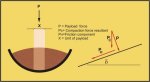
3.1 The profile of the payload trajectory as the material leaves the in bye feed conveyor head pulley is singularly the most important item of information necessary to design an effective transfer chute.
3.2 The position on the head pulley, of the point of departure of the payload determines the shape and type of trajectory.
3.3 A payload departure at "top dead centre" (TDC) of the head pulley will produce a separation of payload of "B" at anyone position on the trajectory.
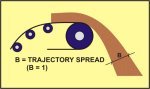
Further the trajectory direction will cause the heavier lumps to flow horizontally from the pulley until overcome by gravity. The higher the pulley speed, the longer the horizontal travel.
Should the payload leave before TDC, the material separation will be greater than "B".
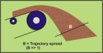
With a large spread of fines and lumps. The heavier lumps will tend to rise on leaving the pulley, before being pulled down by gravity. Thus the material spread will increase with higher pulley speeds.
Should the payload leave the pulley after TDC, then the material spread will be less, and the separation less than "B".
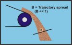
The heavier materials will be directed downwards with the fines, concentrating the payload trajectory and minimising spread.
3.4 The objective of a minimum degradation chute is to limit the amount of energy transferred to the material being chuted, and thus limit the material energy dissipation.
3.5 With a small material spread in the trajectory, the payload remains concentrated so that the fines are present to buffer the lumps. Further the lumps are not traveling in a direction alien to the transfer as would be the case of material leaving at TDC or before.
3.6 No extra energy is required to deflect these lumps from their path, onto anew path. The energy imparted on deflection can cause major degradation and lump breakage.
3.7 The trajectory profile leaving the pulley after TDC will direct the material flow downwards such that the lumps are initially traveling in a direction close to the desired transfer. This means no energy will be spent in controlling the .lumps by deflection, as there is no need.
4. APPLICATION OF THE TRAJECTORY
The payload trajectory is the basis around which the chute is placed in order to land the payload on to the out bye conveyor or receiver.
The basic chute is made up of three sections. Each section being designed and placed such that a minimum of energy is imparted to the material on transfer and thus a minimum of degradation. The material kinetic energy on leaving the feed conveyor should remain constant, with any losses occurring due to friction.
4.1 The first section of the chute, that nearest to the feed conveyor, will be placed parallel to a tangent to the bottom face of the plotted trajectory. This corresponds to the path of the fine materials of the payload.
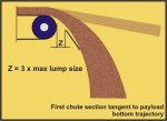
This is done so that the material and initial chute contact is a tangent, with little or no impact of material and no change of material velocity. Thus there will be minimal energy conversion from kinetic in the material to impact on the chute.
4.2 The arc of the bottom plot of the trajectory will meet the proposed tangent line at a point "A". The length of the first chute section will be to this point "A".
At this stage the width of the chute can be closed to control any material spread and to maintain the payload trajectory density. The chute sides need to taper from 300mm wider than the feed belt width done to approximately the out bye belt width or the receiver aperture in order to control spillage and payload density.
4.3 The next section of the chute will transport the bottom trajectory material, whilst the remaining materials land and are brought under control with minimum impact and energy conversion.
This is achieved by the finer materials (bottom trajectory) flowing down the chute and providing a cushion for the larger higher trajectory material to land on.
4.4 The second section angle is greater than the maximum inclination angle required to stop the material flowing.
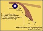
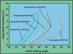
This inclination angle is found by comparing the compaction force of the material in the chute as a result of self mass and the various forces due to moisture adhesion, to the velocity and energy forces.
The angle should be such that. the resultant. Force is sufficient to overcome the chute/material frictional force. The resultant force difference should be minimum in order to minimise degradation.
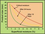
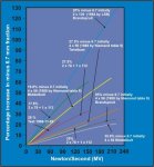
Various graphs have been plotted using different compactions to indicate the critical inclination angles for South African Coals. (These were conducted on -12mm coal.)
 |
 |
 |
 |
4.5 The critical inclination angle will allow material to flow freely with minimum acceleration due to gravity.
4.6 This second section of the chute will be straight with a length such that the top of the material trajectory has reached the chute bottom.
In real terms the material following the top outer trajectory will land onto the finer materials already flowing in the chute.
4.7 The chute second section angle of inclination is such that the top material trajectory will meet the lower material already in the chute at a low angle of incidence, reducing the impact and energy conversion.
Further the finer material sliding on the chute bottom produces an absorbing cushion effect for the larger material.
At this point it is possible to change direction of the material.
4.8 A direct in-line transfer of material will require a short third section of inclination angle such that the material velocity vector is as close to that of the out bye conveyor as possible.
4.9 An oblique or angled transfer will require a change of direction after that point at which all the payload trajectories have landed into the chute straight second section.
The third section length will include the arc of curvature declining at the angle described in 4.8 above, and turning through the required angle with a straight lead onto the centre of the out bye conveyor or receiver
4.10 The minimum transfer height of the chute will be the sum of the elevations of the first two sections and the decline arc. Any height change (increase) should be done by lengthening the lead into the receiver and by increasing the angle of the third section.
4.11 A check calculation should be done on the final length of the last section, to ensure that the material will flow freely on start of the out bye conveyor or receiver (should there be a stoppage and the chute fills up) .
5. DEGRADATION ESTIMATION
5.1 The amount of degradation occurring within a chute can be found using experimental data obtained on various south African Coals over the last 15 years.
5.2 The energy imparted to the payload, as a result of free fall and impact is calculated for each chute section.
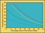
5.3 The corresponding increase in size fraction is found off the curves generated from 5.1 above. Comparing the original and the increase in size fractions will give a percentage figure of the expected degradation the chute will produce.
6. CHUTE MATERIALS AND SECTIONS
6.1 The recommended chute profile is curved. This helps in keeping the material payload in the centre, with the higher energy lumps traveling on the top and the fines providing the base.
6.2 A curved chute profile is easy to manufacture; by rolling sheet into the desired radius. Each section will slot into the previous, and be fastened to provide a smooth inner surface.
6.3 Direction changes are also easily achieved. The rolled sections are cut into segments circumferentially, with alternate segments having one lip dimension twice the other, and vice versa. Then the similar lip segments are all place together, and a perfect angle change is created.
7. CONCLUSIONS
7.1 Degradation of material in a transfer chute results from the change of energy imparted to the material. This may be kinetic, impact or frictional energy.
7.2 The trajectory of the payload will determine the amount of degradation possible. The trajectory results from the in bye conveyor characteristics, such as speed, pulley diameter, conveyor profile.
7.3 By controlling the trajectory, the degradation can also be controlled.
7.4 The trajectory can be controlled by the in bye (leaving) conveyor characteristics as follows:
7.4.1 The payload should leave the head pulley after TCD of the pulley. The most effective being 5 to 10.
7.4.2 The conveyor profile as it approaches the head pulley should form part of an exaggerated curve concentric to the head pulley. Thus the payload will be traveling on a smooth arc on leaving the pulley. This helps maintain the trajectory density and stop spread of payload.
7.4.3 By increasing the pulley diameter, the relative speed difference between top and bottom trajectory profiles will be reduced. Thus the payload will tend to stay together and not spread.
7.4.4 By increasing the pulley diameter, the angular velocity of the payload will increase in comparison to the conveyor speed. This will increase the kinetic energy of the payload, but not necessarily the degradation.
7.4.5 With high conveyor speeds, the payload departure point angle from TDC, on the head pulley should be increased.
7.5 In order to minimise degradation in any transfer chute, the energy change experienced by the material should be an absolute minimum.
Any forced changes of velocity (direction or speed), or payload impact will cause degradation.
Any separation or trajectory spread should be kept to a minimum in order to minimise degradation.
REFERENCES
1. BARCLAY, J.T. Conveyor Belt Research. National Coal Board, 1950-1966.
2. HUDSON, W.G. Conveyors and Related Equipment. John Wiley & Sons, New York. 2nd Edition.
3. STREETS, H. Sutcliffe Manual Of Belt Conveying. W. & R. Chambers, Ltd. Edinburgh.
4. CONVEYOR EQUIPMENT MANUFACTURERS ASSOCIATION. Belt Conveyors for Bulk Materials, 2nd Edition. C.B.I. Publishing Co. Inc., Massachusetts.
5. THE MECHANICAL HANDIJING ENGINEER'S ASSOCIATION. Recommended Practice For Troughed Belt Conveyors.
![]()