Chute Design for Ash Handling
Phil Staples BSc(Mech E) MIME FIMH
Acknowledgements : Bionic Research Institute - Chute Design Conference 1992
ASH HANDLING raises special problems for the chute designer.
This paper identifies the problems and focuses on solutions.
Phil Staples, Project Engineer at Bateman Materials Handling Limited, has designed a wide variety of material handling systems including Kendal Power Station ash handling. He has used Hi-tech conveyor design and dynamic simulation programmes.
THE DEMISE OF THE TRANSFER CHUTE
INTRODUCTION
The transfer chute in a materials handling system using conveyors is essential to maintain continuity of flow from one flight to the next, but it can be shown that the major reason for system unavailability will be a problem with the transfer chute.
To hold a conference on such a topic highlights the degree of sensitivity one holds for the transfer chute. These conferences have produced a multitude of philosophies which attempt to eliminate the transfer problems.
Theories on trajectories, profile, liner materials and impact phenomena abound, however the science of chute design is far from perfected.
We are able to predict, for a given material flow characteristic, theoretical chute angles and flow principals. However, the material seldom performs to specification. Failure to meet specification invariably throws theories out of the window and reduces a highly technical design into a disaster.
In today's environment with rapidly changing requirements there is a need to completely rethink the role of the conveyor. Gone are the days when one could employ a multitude of labourers to clean up the mess and spillage caused by poorly designed or incorrectly predicted transfers.
The introduction of sophisticated chute profiles and liner materials, although improving the situation, will only be as good as the initial design information and the maintenance philosophy employed to keep them to specification.
Therefore there is a need to completely eliminate the transfer point with the introduction of high technology conveying systems.
This paper shows the problems caused by multiple transfers and sets out to establish a thought process which could be employed to reduce the chute problem.
CHUTES USED IN HIGH CAPACITY CONVEYORS
If one looks at the introduction of high speed, high capacity conveyor belts, the need for correct chute design although difficult essential.
High speed, high capacity belts require extensive chute systems to effect transfer. These chute systems have to cater for long material trajectories which have difficulty in catering for the normal cleaning systems employed on such transfer.
Figure 1 shows a typical right angle high speed transfer, where it can be seen that to allow the dribblings from the cleaning system to transfer onto the following belt would require very high chutes, this height must be translated into power and impact associated problems, (such as degradation of the product).
These problems can make the total process of material benefaction financially not viable. Therefore why can we not investigate systems which eliminate multiple transfer points endeavouring through the technology available today to cut out the problem areas.
To highlight my point I have looked at the effects of transfer point design with consideration being given to capital and operating cost, aesthetics and the role of the systems designer in the plant layout, and to highlight the effects of transfer points I have selected a case study for the design of chutes for the transfer of ash.
THE ASH CONVEYING ENVIRONMENT
In the early days of power generation, ash was generally pumped to waste handling facilities, however today with the introduction of the larger power stations ash handling facilities are often required to be designed to cater for capacities of 2000 tph and more.
![]()
Figure 1: High speed belt with right angle transfer
Also, as the stockpiling area for ash dumps tend to be an eyesore, we .often have to move the ash long distances away from the power stations to remote dumping sites.
This makes ash an ideal case study for chute design and to add impact to my theories I have conducted an investigation into the modification required after the initial design and operation of the system an existing ash conveying system.
These modifications were found to be necessary because of the ineffective operation of the original chute work and what really came out of the modification exercise related to major system changes to achieve the best operation.
This revised method of transfer is being extensively used in the other conveying systems, therefore it cannot be claimed as a new technology, what does come out of this approach however is the total layout redesign which was essential for improved availability of the plant.
THE ORIGINAL SYSTEM
The original system is depicted in sketch figure 2.
Typically it shows a trouser leg chute arrangement feeding either of the two following conveyors.
This allows transfer onto one or other conveyor, depending on the available route. There were numerous problems with this type of arrangement which can be seen clearly in figure 3 to 5.

Figure 2: Layout of original system
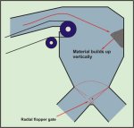
Figure 3 shows the areas where hang-ups occur, firstly the material impacting on the face of the chute will tend to cause packing, this build-up will continue until the build-up either gets too heavy and falls off or the material size changes and causes the build-up to break away.
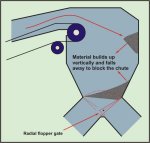
Figure 4 shows the effect of this occurrence with the build-up of material collapsing and blocking one leg of the chute.
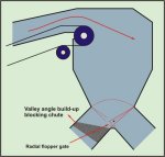
Figure 5 shows the next problems with a chute of this nature. The valley angles tend to build-up with fine ash causing the angle to change and again blocking the chute.
These are the common problems and resulted in the redesign of the total chute system.
REVISED LAYOUT THEORIES
Basically chutes are used to transfer from "A" to "B" with the aim of achieving minimal spillage and maintenance.
Because these aspirations are very rarely achieved, the ineffective chute design proves to be the most basic reason for failure of the conveying system.
As the conveyor layout usually occurs without the input of the systems designer, the feed equipment and routes are devised with little or no consideration for the way in which the transfer must occur.
In the ash conveying systems this plant layout approach and specifically the considered need to have back-up systems for improved availability created the complications which cause system failures.
To achieve duplicity of systems, requires the introduction of additional conveyor flights and transfers. Also there was a need to maintain standby by being able to switch from one flight to the next.
Figure 3: Depicting initial build-up area |
Figure 4: Depicting
initial build-up area which breaks |
|
Figure 5: Depicting valley angle build-up |
|
What if the basic layout brief was to get from point "A" to "B" in the shortest distance with the minimum of transfers, what effect would this have on the overall performance of the plant?
On the negative side we would probably find the aesthetics of the plant displeasing to the eye.
However, on the positive side, we would reduce transfers we would be able to create more inline transfers, and thereby minimise wear areas and build up problems within the chutes.
With conveyor belt considerations, less transfer points will reduce belt cover wear with flights getting longer and thus cycle times increasing.
So I reiterate my initial statement that to eliminate the majority of problems in chute design, we must eliminate the actual transfer point, with the introduction of more sophisticated conveying techniques which would allow us to use a chute to simply contain the flow onto the next stage of transfer.
SPECIFIC CHUTE DESIGN CONSIDERATIONS
Assuming materials flow has been optimised, how can we obtain a satisfactory flow through a chute?
Using ash as the medium which can be considered as a complex material with very erratic flow qualities primarily very wet ash tends to hang on vertical faces especially if it is allowed to impact against them.
The ash will constitute a multitude of flow conditions which can be considered to be a function of moisture content and lump size.
Also to compound the problem, the disposal of the fly ash normally occurs by mixing it with the bottom ash. However we are not able to achieve reasonable mixtures to assist the passage through chutes.
The plant studied incorporated a chute design which because of its height and complexity, tended to cause severe blockages.
The availability of such a system was unacceptable therefore the transfer system was modified to improve the system availability.
REVISED DESIGN SYSTEM
How can one cater for a more effective design?
In the introduction I touched on rationalisation of conveyor flights, the second point was the elimination of high chutes to achieve transfer and the third area was the direct transfer without obstruction.
To expand on these areas, I would like to take you through what I consider to be the correct philosophy in designing a system of this type.
CONVEYING ROUTE
Sketch figure 6 shows a common approach to the collection of ash from a power station.
It can be seen that the ash travels a complete circle prior to embarking on its path to the ash dumps. Aesthetically it looks like a complete and correctly designed system. But we also see that there are nine transfer points before entering the overland system.
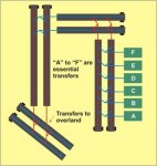
Assuming that 6 of these transfer numbered A to Fare essential to extract the ash from the boiler onto the overland system, what would be the effect of eliminating at least two of the three remaining transfer points.
We see the type of system depicted in figure 7 where instead of the three stage collect conveyor a simple single stage is introduced which through correct technological efforts we are able to remove two of the three troublesome transfer points.
|
Figure 6: Showing the common approach of ash handling |
Figure 7: Showing the elimination of 2 of the transfer points |
I accept that the lines of the conveyor are not straight and true however this system will statistically produce a higher availability.
CHUTE SELECTION
The next point is the elimination of the high transfer for the trouser leg chute. What possible reason is there for introducing a split chute design? (Refer to figure 8)
The only reason I can suggest is initial capital cost. If during the design process consideration was given to operating and maintenance costs and system availability we would never see a complex bifurcated, chute design.
Therefore it should be possible for the end user to specify out the type of design.
The specification philosophy of eliminating troublesome equipment selection is quite common.
Examples of this are the use of worm boxes on drives under 45 kW only, the use of fluid couplings on drives of over 22 kW, etc.
Thus why not the elimination of a flopper gate in all chute conveying sticky wet materials. This would make a dramatic improvement on the system design.
We are advancing this way in some installations but because of cost restraints this is not a rule and in competitive tender situations is always ignored unless specified by the enlightened client.
TRANSFERS WITHOUT OBSTRUCTION
This obviously is an ideal however the closer we come to achieving this type of transfer the closer we will come to eliminating transfer point failures.
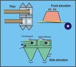
Figure 8: Layout of final design (Chutes)
Many papers have been written extensively covering the need to use anti-degradation chutes in coal flow systems this type of solution will not be effective in ash handling and the handling of other sticky materials. Here we must completely unrestricted flow. The most effective way of achieving this and achieving multiple transfers is with the use of the moving head design.
This has now become a norm in the design of ash handling plants and couple this to the modifications to layouts with the rationalisation of conveyor flights and we have the basis for a well designed system.
The study into the effects of changing from bifurcated chutes to moving heads is showing marked improvement in system availability. Although it its early days, we anticipate that there will be very few designs contemplated with chutes operating as no more than a containing element.
The high cost savings which could be realised from this type of approach are difficult to quantify at concept stage, however when the total picture comes into play the elimination of the transfer point must be considered essential with all systems designers.
CONCLUSION
The need to transfer makes the conveying system one of the problem areas in a plant operation, often being the cause of high unavailability.
The minimisation of transfers by the introduction of more sophisticated conveyor profiles will in the long term have a major influence in the improved efficiency and thus improved performance of any plant.
We must go away from the standard straight line conveying profile with the introduction of the high technology conveyors.
The elimination of a transfer point with the introduction of a curved conveyor must now become a normal approach.
The scissors transfer to obtain height must be replaced by the high angle sandwich belt design.
Finally, sticky, dusty materials must be contained in pipe conveyors or similar
![]()