Extraction |
Narrow Chute |
Verticle Chute |
|
An arrangement
of sonic "Dry Fog" |
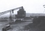
Screen and bin feed
application |
Same application with DRY FOG Dust Suppression |
|
Dust Control at Transfer Points
Chris Rowland
Acknowledgements : Bionic Research Institute - Chute Design Conference 1992
DUST control at transfer points requires a good, basic mechanical design.
This paper focuses on problems which may be overlooked when designing for dust control. Various dust control options are reviewed.
Christopher St. John Rowland is Managing Director of Sonicore Systems S.A. He has been instrumental in bringing various new dust control systems into use in Southern Africa.
INTRODUCTION
The presence of dust is a fact of life in many industries which handle or process a product such as coal, mineral ores and many others.
So as not to become too general in trying to address the Problem, Causes and Solutions of Dust Control in virtually every situation, I will confine myself to dust control regarding:-
- Surface Mechanical Handling plant typically including crushers, screens, transfer points, surge and storage bins etc.
- The handling of considerable volumes or tonnage's of product where the intention is to handle it as cost effectively as possible, where dust is a nuisance and where ancillary dust control plant is generally regarded as a non-productive cost to be minimised.
For the purposes of this seminar, I ask you to accept that the problem is Dust and it's containment. So this paper is concerned with Causes and Solutions.
In addressing Causes, I will look at Gravity, Air and Airflow and the element of Time with a short preamble of what dust and dust control is.
Regarding Solutions, I will review the ancillary dust control system options available preceded by what can and should be done before anyone considers these systems.
Finally, I will describe and analyse a few examples to illustrate the points raised.
WHAT IS DUST?
Handbooks, dealing with ventilation and dust control, mostly define dust as product particles from 0,1 to 100 m.
Within this range, we have the restorable dust up to 7 m and while total dust is to be controlled to specified threshold limits, this restorable range is the more important, especially where the dust is toxic.
Restorable dust is not easily visible. Thus the absence of visible dust does not mean there is no dust at all.
In broad conversational terms, dust is anything which escapes from a mechanical handling plant to become nuisance dust. So this too needs to be controlled.
As the figures in Table I will be used at various times during the rest of the paper, I quote the fall speeds of product particles of , quartz, reproduced from the publication "Environmental Engineering in S.A. Mines" (Ref. 1)
TABLE 1
Micron Size
Fall Speeds m/s
250
4.977
100
0.796
50
0.199
20
3.18 * 10-2
7
3.90 * 10-3
1
7.964 * 10-5
g
9.79
WHAT IS DUST CONTROL?
Dust Control is basically two things. One, the prevention or limitation of dust being created. Two, the prevention or limitation of dust being liberated.
As prevention is largely impossible, limitation must be our focus and that focus must not be directed only at liberation. As dust is inevitable does not mean the only solutions lie in containing and capturing it.
So my next step is to look at what influences both the creation and liberation of dust, from the point of view of what appears to be being overlooked or ignored.
GRAVITY
Reference to Table 1 will show that while g is 9,79 m/s, particles of 250 m and below do not fall at this speed. The speeds given are terminal velocities, the maximum speed they attain.
But my point in introducing gravity is to remind us that the effect of gravity is that particles gain energy which has to be lost in some way. In the type of plants we are considering, the energy is dissipated by product degradation. It breaks up. It crushes particles into dust. It breaks off dust and small particles.
The greater the fall, the more energy is available. Some of the energy goes into moving dust and small particles in all directions. Many of these impact on chute sides and on falling product and they become even smaller. Above all, they become airborne. Dust is mainly liberated on impact besides the fact that it's also created at the point of impact.
AIR AND AIR FLOW
The presence of air is another factor and with reference to Table 1 again, it's presence influences the fall rate of particles. So, if we consider the cascade of product from a conveyor, the longer it is exposed to air, the more segregation which will occur.
We now have the situation of dust being created and liberated by the impact plus it being liberated through segregation by the presence of air in the chute.
The segregation effect will be reduced because the cascade draws air with it to produce a flow of air through the chute. But while we have this on the plus side, we must look at what happens next.
Because the air has mass as well as induced velocity, the first place to consider, especially in conveyor to conveyor transfer chutes, is the bottom of the vertical section. Pressure will build up around the impact area anyway. It will be more severe if we try to turn all the air through 270 or more and not allow a good percentage to flow easily into the discharge chute.
But because we have airborne dust, the discharge chute cross sectional area is most important to avoid the air being accelerated out of the chute. If anything, we must aim to decrease the speed caused by the cascade and length of fall.
An ideal is to increase the negative pressure zone in the vertical chute by sealing off as much of the inlet or head chutes as is practical. This will reduce ingress air and go some way to relieve the pressure around the point of impact.
TIME
Time is all important. All of what I have said relates back to speeds and since we are at the point of having airborne dust in the discharge chute or a transfer point, it should be obvious, that we now need to allow particles to settle out.
The premise we use is that an adequate discharge chute design ensures that the air speed is about the same as the belt speed in conveyor to conveyor transfer chutes. Obviously if the chute is bigger or smaller, this will change. It will also change according to the volume of product being conveyed.
In the following table, I illustrate the length of the chute needed to allow various quartz particles to fall 1 metre assuming a belt speed of 3.0 m/s, the chute length
TABLE 2
PARTICLE SIZE
LENGTH OF CHUTE (Metres)
(* Belt Speed)
250
0.603
0.200
100
3.769
1.256
50
15.075
5.025
20
94.340
31.446
7
1
Main Product
0.306
0.102
The above has not been proved by any form of tests and is intended only to illustrate the perspective needed in design of chutes which is to recognise that the chute volume plays a significant role.
From the aspects presented so far, we can now look at the probable limits of mechanical means of dust control.
The main point because of it's cost implications, is the length of discharge chutes on conveyor to conveyor transfer points. For products having An equivalent or greater mass density, 50 m 50 dust particle capture is already a problem. The figures in Table 2 suggest somewhere around 75 m or a chute length around 2,5 to 3.0 times belt speed.
The above pre-supposes that the mechanical design has addressed the questions of induced airflow and it's reduction for, if these have not been limited, we are back to square one.
So basically, the point is that dust control starts with good mechanical design in order to limit the demands on the additional dust control systems needed to comply with the law.
The point also is that no mechanical handling or processing plant can be designed where mechanical means alone are used unless the entire plant is enclosed in a building or it is virtually or actually a pneumatic conveying system.
SOME MECHANICAL OPTIONS
The most obvious mechanical dust control device is using slides as these limit the energy gained and generally tend to reduce the airflow through transfer chutes. Above all, they limit the degree to which dust can become airborne.
The use of crash boxes in vertical chutes has a lot of merit if slides cannot be accommodated, but their use introduces many more impact zones to increase product degradation, especially if the product is susceptible to breaking up.
However, if we review Tables 1 and 2, we quickly come to the answer that total dust control, by mechanical means, is not possible.
OTHER CONTROL OPTIONS
Having established that mechanical design can influence the demand on final dust control system, we must recognise that this only presents the potential of having a lower cost of the final dust control system. There is little point in investing in the best mechanical design if we are going to ignore the boundary that this establishes, by specifying excessive performance levels for the dust control plant.
If the final system is to be Dust Extraction, the decision needs to be made whether the 75 m particles and smaller are the targets or whether it's acceptable to lift off anything up to 1.0 mm. This decision is important because if we are to use bag filters, the dust load and size are important design factors. If large particles are being captured, duct velocities need to be higher to prevent them falling out in the ducting. Higher velocities mean increased fan power.
Of course, good mechanical design and effective belt seals have a bearing on basic extraction volumes. Extraction itself may reduce discharge chute lengths, but these should still be long enough to ensure that larger particles are not extracted.
If the collector device is to be a Wet Scrubber, the efficiency needs to be specified. The higher the efficiency, the higher the fan power. If the efficiency is too low, the overall capital, operating, maintenance and dust disposal costs may make dust suppression a cost effective option as neither the Wet Scrubber nor dust suppression systems offer perfect dust control. A low efficiency scrubber may merely transfer the dust problem to the stack.
Another option to control dust is Dust Suppression which does rely on good mechanical design to achieve results which comply with legislation. But it must be always remembered that the objective of suppression is to achieve control results within threshold limits at a cost which should be attractive to plant owners. No suppression system will achieve perfect control results, but then no extraction system does either.
There are two types of suppression systems. The first is termed wet suppression and it's objective is to bind dust and particles to the main product and prevent liberation during handling. It has the advantages of being applied at virtually any point suitable. It has the shortcomings that to wet the whole product and all the dust, the number of application points may be extensive leading to considerable water usage - and chemicals, if they are used - and, potentially, excess moisture content in the product. They cannot be used on products which have any affinity to water.
The second type is the mist or fog type system which has the objective of dampening only the dust liberated to cause it to increase in mass and fall out. So, it's water usage should be minimal, even with there being a considerable number of dust control points.
The proven theory of these systems is that if the dust and water particles are about the same size, they can and do bond. But as we are concerned with dust, particularly in the 1 to 7 m range, this means droplets must be in this range as well.Small droplets are created by energy being released at the atomising nozzle. If this energy is insufficient, small droplets must then develop by evaporation, which takes time. If the droplets are too large, they may only be small enough by the time they are carried out of the chute system along with the dust on the air-stream.
So in selecting a mist or fog system, it must be capable of producing small enough droplets and enough of them to ensure capture of dust within the chute system. Not all systems can do this.
SUMMARY
Dust Control is not merely the responsibility of the Oust Control system supplier, but of the user to :
- select the system he intends to use as a final control system, and
- ensure that that system is not called upon to deal with dust created and liberated by the mechanical design being poor or inadequate.
Dust creation cannot be eliminated, but it can be limited. Dust Control system options can be cost effective, but their selection should include investigation into the long term cost of operation and maintenance as well as their effectiveness in terms of meeting the current or anticipated legislation on threshold limits.
REFERENCES
Ref. 1 "Environmental Engineering in South African Mines" by The Mine Ventilation Society of South Africa 1982.
EXAMPLES
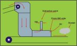
1) A conveyor to conveyor transfer point, carrying a hot ( 50C) product of size - 3 mm. Belt speeds around 2.0 m/s. The discharge chute was approximately 8 metres. The vertical fall was 6 to 7 metres. (See Figure 1)
The result of this design was that there was a column of airborne dust which left the discharge chute at such a velocity that it began to dissipate only after it had travelled nearly 10 metres, causing a major dust problem.
The causes were the unrestricted head chute allowing air to be drawn in, the vertical fall causing additional air to be drawn in and accelerated, the vertical fall segregating dust and product and finally, a discharge chute which tended to accelerate rather than reduce the air speed generated within the system.
A further cause of increased air speed was the product temperature which increased the air volume by as much as 10 percent as there was sufficient residence time for this to occur.
The solution to this problem basically lay in a complete redesign mechanically.
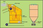
2) A coal plant, with many conveyor transfer points, emitting dust from the head chutes, despite there being a suppression system, also experiencing chute blockages. (See Figure 2)
The cause primarily was that the mechanical plant contracted was allowed to use his in-house standards. The users standards were waived.
The discharge chutes were so small that the product virtually choked the chutes. This in turn led to a back pressure in the head chute forcing incoming air to exit from the head chute carrying any dust which had become airborne. Air speeds prevented the suppression system from doing any good at all and when the chute became choked, the suppression system tended to damp the coal. This damping became progressively worse until blockage occurred.
The solution was to return the mechanical design to at least the users standards. This would allow airflow and prevent the mist suppression system from causing damping of the main product or chutes.
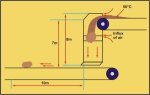
3) A transfer chute emitting dust from the discharge despite the presence of an extraction system. See Figure 3.
The cause was the open end of the discharge chute allowing air to be drawn in along the roof of the discharge chute. Further, the extraction branch pipe of 150 mm was fitted directly to the chute roof, no transition piece was used resulting in localised dust capture in the 600 wide chute.
The solution was to close off the discharge chute and all other openings and install a take-up hood to increase the dust capture area.
Extraction |
Narrow Chute |
Verticle Chute |
|
An arrangement
of sonic "Dry Fog" |
Screen and bin feed
application |
Same application with DRY FOG Dust Suppression |
|
![]()