|
Modern Technological Developments
in the Storage and Handling of Bulk Solids
|
|
A. W. Roberts
Director, School of Engineering, Director TUNRA Ltd,
The University of Newcastle, NSW, Australia
Acknowledgements : Bionic Research
Institute - Chute Design Conference 1992
SUMMARY
This paper presents an overview of some modern developments
in the technology of bulk solids handling. An overview of storage system design
including bins and gravity reclaim stockpiles is presented and aspects of feeder
performance is given. The importance of wall or boundary friction in hopper and
chute design is discussed and the associated adhesion and wear characteristics
are outlined in relation to the selection of appropriate lining materials.
Problems due to flow instabilities during discharge from coal bins are reviewed;
these flow pulsations may give rise to severe dynamic loads on the bin
structure.
1. INTRODUCTION
Throughout the world bulk materials handling operations
perform a key function in a great number and variety of industries. While
the nature of the handling tasks and scale of operation vary from one
industry to another and, on the international scene, from one country to
another according to the industrial and economic base, the relative costs of
storing, handling and transporting bulk materials are, in the majority of
cases, very significant. It is important, therefore, that handling systems
be designed and operated with a view to achieving maximum efficiency and
reliability .Directly related to these objectives is the ongoing need for
engineers and those involved in the operation of handling plants to be kept
informed of the latest research and technological developments relevant to
their industry and, at the same time, contributing to these developments and
to the dissemination of information in the light of their own experiences.
The theme embodied in the foregoing remarks is of
particularly relevance to Australia in view of the heavy dependence on bulk
handling operations. While these operations range across the broad spectrum
of industries, of prime importance are the mining and mineral processing
industries which handle coal and mineral ores in large tonnages. These
industries make a major contribution to Australia's export earnings and
economic growth.
Over the past three decades much progress has been made
in the theory and practice of bulk solids handling. Reliable test procedures
for determining the strength and flow properties of bulk solids have been
developed and analytical methods have been established to aid the design of
bulk solids storage and discharge equipment. There has been wide acceptance
by industry of these tests and design procedures and, as a result, there are
numerous examples throughout Australia of modem industrial bulk solids
handling installations which reflect the technological developments that
have taken place.
Notwithstanding the current situation, the level of
sophistication required by industry demands, in many cases, a better
understanding of the behaviour of bulk solids and the associated performance
criteria for handling plant design. Experience indicates that the solution
one problem which leads to an improvement in plant performance often exposes
other problems which need to be solved. It becomes progressively clearer
that there are many gaps in the present state of knowledge where further
research is necessary.
The purpose of this paper is to briefly highlight the
present state of knowledge associated with bulk handling and indicate where
further work is necessary. The material presented is based on the research
conducted by Tunra Bulk Solids Handling Research Associates of the
University of Newcastle. This research group has been involved in bulk
handling research and industrial consulting for some considerable time and
in recent years has been .supported by research grants obtained from AMIRA.
2. HANDLING PLANT DESIGN - BASIC CONCEPTS
2. 1 General Remarks
The design of handling plant, such as storage bins,
gravity reclaim stockpiles, feeders and chutes is basically a four step
process:
- Determination of the strength and flow
properties of the bulk solids for the worst likely flow conditions
expected to occur in practice.
- Determination of the bin, stockpile, feeder or
chute geometry to give the desired capacity, to provide a flow
pattern with acceptable characteristics and to ensure that discharge
is reliable and predictable.
- Estimation of the loading on the bin and
hopper walls and on the feeders and chutes under operating
conditions.
- Design and detailing of the handling plant
including the structure and equipment.
The general theory pertaining to gravity flow of bulk
solids and associated design procedures are fully documented [1-4]. For
the purpose of the present discussion, the salient aspects of the
general philosophy are briefly reviewed.
2.2 Modes of Flow in Bins of Symmetrical Geometry
As is now well established, there are two basic modes
of flow, namely, mass-flow and funnel-flow. These are illustrated in
Figure 1.
In mass-flow, the bulk solid is in motion at every
point within the bin whenever material is drawn from the outlet. There
is flow of bulk solid long the walls of the cylinder (the upper parallel
section of the bin) and the hopper (the lower tapered section of the
bin). Mass-flow guarantees complete discharge of the bin contents at
predictable flow rates. It is as a first-in, first-out flow
pattern; when properly designed, a mass-flow bin can re-mix the bulk
solid during discharge should the solid become segregated upon filing of
the bin. Mass-flow requires steep, smooth hopper surfaces and no abrupt
transitions or in-flowing valleys.
Mass-flow bins are classified according to the hopper shape and associated flow pattern. The two main hopper types are conical hoppers which operate with axi-symrnetric flow and wedged-shaped or chisel-shaped hoppers in which plane-flow occurs. In plane-flow bins, the hopper half-angle a will usually be, on average, approximately
8 to 10 larger than the corresponding value for axi-symmetric bins with conical hoppers.
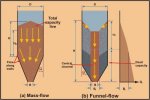
Figure 1. Modes of Flow
Therefore, they offer larger storage capacity for the same head room than the axi-symmetric bin, but this advantage is somewhat offset by the long slotted opening which can give rise to feeding problems. The transition hopper, which has plane-flow sides and conical ends, offers a more acceptable opening slot length. Pyramid shaped hoppers, while simple to manufacture, are undesirable in view of build-up of material that is likely to occur in the sharp corners or in-flowing valleys. This may be overcome by fitting triangular-shaped gusset plates in the valleys.
Funnel-flow occurs when the hopper is not steeply sloped and the walls of the hopper are not smooth enough. In this case, the bulk solid sloughs off the top surface and falls through the vertical flow channel that forms above the opening. Flow is generally erratic and gives rise to segregation problems. Flow will continue until the level of the
bulk solid in the bin drops an amount HD equal to the draw-down. At this level, the bulk strength of the contained material is sufficient to sustain a stable rathole of diameter
Df as illustrated in Figure 1(b). Once the level defined by HD is reached, there is no further flow and the material below this level represents 'dead' storage. This is a major disadvantage of funnel-flow. For complete discharge, the bin opening needs to be at least equal to the critical rathole dimension determined at the bottom of the bin corresponding to the bulk strength at this level. However, for many cohesive bulk solids and for the normal consolidation heads occurring in practice, ratholes measuring several metres are often determined. This makes funnel-flow impracticable. Funnel-flow has the advantage of providing wear protection of the bin walls, since the material flows against stationary material. However it is a 'first-in last-out' flow pattern which is unsatisfactory for bulk solids that degrade with time. It is also unsatisfactory for fine bulk solids of low permeability. Such materials may
aerate during discharge through the flow channel and this can give rise to flooding problems or uncontrolled discharge.
The disadvantages of funnel-flow are overcome by the use of expanded-flow, as illustrated in Figure 2. This combines the wall protection of funnel-flow with the reliable discharge of mass-flow. Expanded-flow is ideal where large tonnages of bulk solid are to be stored. For complete discharge, the dimension at the transition of the funnel-flow and mass-flow sections must be at least equal to the critical rathole dimension at that level. Expanded-flow bins are particularly suitable for storing large quantities of bulk solids while maintaining acceptable head heights. The concept of expanded-flow may be used to advantage in the case of bins or bunkers with multiple outlets.
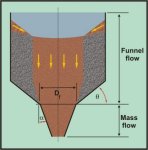
Figure 2. Expanded Flow
Generally speaking, symmetric bin shapes provide the best performance. Asymmetric shapes often lead to segregation problems with free flowing materials of different particle sizes and makes the prediction of wall loads very much more difficult.
2.3 Mass-Flow and Funnel-Flow Limits for Symmetrical Bins
(a) Established Theory due to Jenike
The mass-flow and funnel-flow limits have been
defined by Jenike on the assumption that a radial stress field
exists in the hopper [1,2]. These limits are well known and have
been used extensively and successfully in bin design. The limits for
axi-symmetric or conical hoppers and hoppers of plane-symmetry
depend on the hopper half-angle α, the effective angle of
internal friction 8 and the wall friction angle Φ. Once the
wall friction angle and effective angle of internal friction δ
have been determined by laboratory tests, the hopper half-angle may
be determined. In functional form
α = ( Φ,δ ) -------------------
(1)
The bounds for conical and plane-flow hoppers are
plotted for three values of δ in Figure 3. In the case of
conical or axi-symmetric hoppers, it is recommended that the
half-angle be chosen to be 3 less than the limiting value. For
plane-flow, the bounds between mass and funnel-flow are much less
critical than for conical hoppers. In plane-flow hoppers, much
larger hopper half angles are possible which means that the
discharging bulk solid will undergo a significant change in
direction as it moves from the cylinder to the hopper.
For plane-flow, the design limit may be selected;
if the transition of the hopper and cylinder is sufficiently
radiused so that the possibility for material to build-up by
adhesion is significantly reduced, then a half-angle 3 to 4
larger than the limit may be chosen.
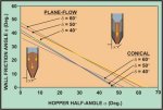
Figure 3. Limits for Mass-flow for Conical and
Plane-Flow Channels
(b) Modification to Mass-Flow Limits - More Recent
Research
Since in the work of Jenike, flow in a hopper is
based on the radial stress field theory, no account is taken of the
influence of the surcharge head due to the cylinder on the flow
pattern developed, particularly in the region of the transition. It
is been known for some time that complete mass-flow in a hopper is
influenced by the cylinder surcharge head. For instance, there is a
minimum level Hcr which is required to enforce mass-flow in the
hopper [5]. For the mass-flow bin of Figure 1(a), this height ranges
from approximately O.75D to 1.0 D.
More recent research has shown that the mass-flow
and funnel-flow limits require further explanation and refinement.
For instance, Jenike [6] published a new theory to improve the
prediction of funnel-flow; this led to new limits for funnel-flow
which give rise to larger values of the hopper half-angle than
previously predicted, particularly for high values of the wall
friction angle. In the earlier theory, the boundary between
mass-flow and funnel-flow was based on the condition that the
stresses along the centre line of the hopper became zero. In the
revised theory the flow boundary is based on the condition that the
velocity becomes zero at the wall.
In a comprehensive study of flow in silos, Benink
[7] has identified three flow regimes, mass-flow, funnel-flow and an
intermediate flow as illustrated in Figure 4. Whereas the radial
stress theory ignores the surcharge head, Benink has shown that the
surcharge head has a significant influence on the flow pattern
generated. He derived a fundamental relationship for Hcr in terms of
the various bulk solid and hopper geometrical parameters, notably
the H/D ratio of the cylinder and the effective angle of internal
friction δ. Benink developed a new theory, namely the arc
theory, to quantify the boundaries for the three flow regimes.
This theory predicts the critical height Hcr at which the flow
changes.

Figure 4. Flow Regimes for Plane-Flow Hopper defined by
Benink [7]
2.4 Bin Geometry for Mass-Flow
(a) Basic Considerations
Basically the aim in mass-flow design is to
determine the hopper geometry to give reliable flow at all times at
the required discharge rate. Primarily, the requirement is to
determine the hopper half angle α, which defines the slope with
respect to the vertical, and opening dimension B.
Undisturbed storage time and changes in moisture
content can significantly influence the unconfined yield strength of
the bulk solids. By way of illustration, the critical hopper opening
dimension B for three Hunter Valley coals plotted as a function of
moisture content are shown in Figure 5. This figure shows three coal
samples, Sample (1) being a Raw Open Cut Coal, Sample (2) a washed
version of (1) and Sample (3), a blend of (2). The high strength of
the raw, unwashed coal is clearly evident. Experience has shown that
the peak bulk strength of coal may occur at a moisture content
somewhere between 70% and 90% of the saturation limit.
(b) Influence of Wall Friction
Since an increase in both the normal wall
pressure and consolidation pressure accompany an increase in hopper
span, then the corresponding decrease in wall friction angle will
permit the hopper half angles to be increased. Hence it is possible
to calculate a hopper half angle α as a function of hopper span
or opening dimension as indicated in Figure 6. As shown, the half
hopper angles for both wedge and conical hoppers tend towards
limiting values as the opening dimension increases.
2.5 FUNNEL-FLOW AND EXPANDED-FLOW GEOMETRY
As previously discussed, it is necessary to compute
the critical or minimum diameter Df for an unstable pipe or
"rat-hole" from which the minimum bin opening for funnel-flow
or the transition dimension for expanded-flow is determined. The
transition dimension for expanded-flow refers to the transition of the
mass-flow hopper with the upper funnel-flow section of the bin.
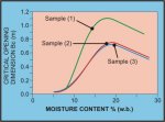
Figure 5 Critical Opening Dimension BCR as a Function of
Moisture Content for Three Coal Samples -Stainless Stee1304-2B Lining

Figure 6 Variation of Hopper Half-Angle with Span for Coal
on 304-2B Stainless Steel
3. BIN WALL LOADS
In bin design, the prediction of bin wall loads continues
to be a subject of some considerable complexity. In view of its obvious
importance it is a subject that has, in recent years, attracted a good deal
of research effort. Currently, there are several research groups in various
countries of the world directing their attention to the study of bin wall
loads using a range of analytical and numerical techniques such as those
involving finite element analysis. Despite the widely varying approaches to
the analysis of bin wall loads, it is clear that the loads are directly
related to the flow pattern developed in the bin.
The flow pattern which a mass-flow bin exhibits is
reasonably easy to predict and is reproducible. However, in funnel-flow bins
the flow pattern is more difficult to ascertain, especially if the bin has
multiple outlet points, the loading of the bin is not central and/or the
bulk solid is prone to segregation. Unless there are compelling reasons to
do otherwise, bin shapes should be kept simple and symmetric.
3.1 Wall Pressures in Mass-Flow Bins
In mass- flow bins, the pressures acting normal to
bin walls vary from the static or filling conditions to the dynamic or
flow conditions. The pressure distributions are well defined and, using
current theories [3-4], may be predicted with confidence.
It is to be noted that in the flow situation a high
switch stress occurs at the transition. The magnitude of this switch
stress is several times the corresponding static value. Further, it may
also be noted that the wall pressures acting in the cylindrical section
during flow may be higher than the static values. For a perfectly
parallel cylinder, the wall pressures during flow would be the same as
the static values. However, when imperfections such as weld projections
or plate shrinkage give rise to flow convergences, peak stresses
occur. The stresses are taken into account by computing the locus of all
such possible peak pressures.
3.2 Wall Pressures in Funnel Flow Bins
While for design purposes wall pressures in
symmetrical funnel-flow bins may be determined with a high degree of
confidence, the wall loading in bins with multiple outlets and eccentric
discharge points are far more difficult to estimate. Under eccentric
discharge, the walls are subject to bending moments and hence, bending
stresses in addition to hoop stresses [8]. In the case of tall grain
silos, the use of anti-dynamic tubes offers significant advantages in
controlling the wall pressures, both in the case of symmetrical
funnel-flow silos as well as silos with eccentric load out points
[9-10].
3.3 Australian Standard for Loads in Bulk Solid Containers
In recent years there has been considerable activity
in several countries of the world in the development of new or revised
codes for bin wall loads. Of particular note is the preparation of the
new Australian Standard "AS-89138 Loads for Bulk Solids Containers
" [11], which represents a major milestone. This publication
presents a very comprehensive review of the loads acting in bin and silo
walls under a the full range of operating conditions likely to occur in
practice. As an example, Figure 7 shows the wall loadings determined on
the basis of this new Standard for a large coal bin having seven
outlets; the pressure profiles correspond to one possible mode of
discharge involving the operation one eccentric outlet only.
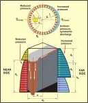
Figure 7. Circumferential Pressure Variation due to
Operation of One Eccentric Outlet
4. FEEDING OF BULK SOLIDS
4.1 Use of Feeders to Control Discharge
In general, a feeder is a device used to control the
flow of bulk solids from a bin. While there are several types of feeders
commonly used, it is essential that they be selected to suit the
particular bulk solid and the range of feed rates required. It is
particularly important that the hopper and feeder be designed as an
integral unit so as to ensure that the flow from the hopper is fully
developed with uniform draw of material from the entire hopper outlet.
For example, in the case of a screw feeder, this is achieved by using
selected combinations of variable pitch, variable diameter and variable
core or shaft diameter.
In the case of a belt or apron feeder, a tapered
opening is required as illustrated in Figure 8. The use of vertical
triangular plates in the hopper bottom are an effective way to achieve
the required taper. The gate on the front of the feeder is used only for
flow trimming and not for controlling the flow rate. The height of the
gate is adjusted to give the required release angle Ψ to achieve
uniform draw along the slot. Once correctly adjusted, the gate is then
fixed in position and the feed rate is controlled by varying the speed
of the feeder.
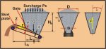
Figure 8. Belt and Apron Feeder
In the case of vibratory feeders, there is a tendency
for feed to occur preferentially from the front. To overcome this
problem, it is recommended that the slope angle of the front face of the
hopper be increased by 5 to 8 as illustrated in Figure 9.
Alternatively, the lining surface of the front face in the region of the
outlet may selected so as to have a higher friction angle than the other
faces.
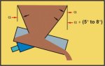
Figure 9. Vibratory Feeder
4.2 Determination of Feeder Loads and Power
The determination of feeder loads and drive powers
requires a knowledge of the stress fields generated in the hopper during
the initial filling condition and during discharge. Under filling
conditions, a peaked stress field is generated throughout the entire bin
as illustrated in Figure 10. Once flow is initiated, an arched stress
field is generated in the hopper and a much greater proportion of the
bin load is supported by the hopper walls. Consequently, the load acting
on the feeder substantially reduces as shown in Figure 10.
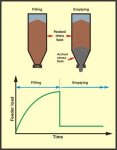
Figure 10. Load Variations on a
Feeder
It is quite common for the load acting on the feeder
under flow conditions to be in the order of 20% of the initial load. The
arched stress field is quite stable and is maintained even if the flow
is stopped. This means that once flow is initiated and then the feeder
is stopped while the bin is still full, the arched stress field is
retained and the load on the feeder remains at the reduced value. The
subject of feeder loads is discussed in some detail in Refs. [12-15].
The loads on feeders and the torque during start-up may be controlled by
ensuring that an arched stress field fully or partially exists in the
hopper just I prior to starting. This may be achieved by such procedures
as:
Cushioning in the hopper, that is leaving a
quantity of material in the hopper as buffer storage.
Starting the feeder under the empty hopper before
filling commences.
Raising the feeder up against the hopper bottom
during filling and then lowering the feeder to the operating condition
prior to starting. In this way an arched stress field may be partially
established.
5. GRAVITY RECLAIM STOCKPILES
5.1 Draw-Down Performance Considerations
Gravity reclaim stockpiles when properly designed,
operate under expanded-flow, as illustrated in Figure 11. This shows
discharge through a single opening in a stockpile. Discharge will take
place by funnel-flow in the main body of the stockpile, with the flow
expanded through the mass-flow hopper. In this way, reliable flow to the
feeder is assured. Flow will continue until the draw-down head hD is
reached; flow then ceases as a stable pipe or rathole is formed. The
draw-down is consistent with critical rathole dimension Df which forms
at that level. The shape of the rathole depends on the consolidation
conditions within the stockpile, the particle or lump size range of the
stored bulk solid and the moisture content.
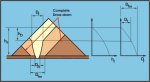
Figure 11. Draw-Down in
Stockpile
Complete draw-down, as illustrated in Figure 11,
corresponds to the critical rathole dimension Dfm at the base of the
stockpile. For complete draw-down to occur, it is necessary for the
diagonal dimension of the hopper transition to be at least equal to Dfm
Since values of Dfm may be several metres, often it is not practical or
economical to employ a large enough hopper to achieve complete
draw-down. For this reason, the design of stockpile reclaim hopper and
feeder systems requires a full consideration of the various options
available with a view to optimizing the reclaim performance within
specified practical and economic limits.
5.2 Use of Multiple Hoppers
The use of multiple hopper systems which allows for
intersection of the flow channels to occur, as illustrated in Figure 12,
provides for good reclaim performance to be achieved. By varying the
separation distance X, an optimum spacing can be established as
illustrated in Figure 13.
5.3 Live Capacity versus Moisture Content
In a programme of research conducted at the
University of Newcastle 16,17], studies have been performed using a
conical stockpile model which allowed different feeder configurations to
be examined. Although the scale of the model relative to actual
stockpiles is very small (a factor of 1/50 in one case of an iron ore
stockpile), the predicted performance base on the model studies were
surprisingly good. The modelling process involves scaling the particle
size and adjusting the moisture content of the bulk solid to reproduce,
as close as possible, the same arching characteristics in the model feed
hoppers as would occur in the full scale stockpile.

Figure 12. Improved Reclaim Performance using Double Reclaim
System
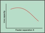
Figure 13. Live Capacity versus Feeder
Separation
By way of illustration, Figure 14 shows the reclaim
performance for a double hopper system for five different coal moisture
contents. Several tests were conducted over a range of hopper separation
lengths. The separation of the hopper is measured by the distance S
between the inner edges of the two hoppers which are equi-distant on
each side of the stockpile centreline.
The data in Figure 14 show the reduction in live
capacity with increase in moisture. This is to be expected because the
strength of the bulk solid increases with moisture content. The results
also show that there is an optimal separation length for the two-hopper
system where maximum reclaim of material can be expected. This optimal
distance being dependent on the moisture content of the bulk material.

Figure 14. Double Hopper Stockpile Live Capacity for Model
Stockpile using Coal. Hopper length at transition = 12Omm, width = 100mm
5.4 Loads on Reclaim Hoppers and Feeders
The loads on reclaim hoppers and feeders and the
corresponding power to drive the feeders varies from the
"initial" to the flow condition as discussed in Section
4. The loads are illustrated in Figure 15. The initial load will
correspond to the case when the stockpile or crater above the feeder is
filled. The surcharge load Qs will depend on the consolidation condition
of the bulk solid in the stockpile. The worst case corresponds to the
hydrostatic pressure. However, if a rathole has been pre-formed, then
the surcharge load will be reduced. When an arched or flow stressed
field has been formed within the mass-flow reclaim hopper, the load on
the feeder will be greatly reduced. Confirmation of the load conditions
acting on reclaim hoppers has been obtained from the model stockpile
tests.
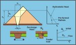
Figure 15. Loads on Stockpile
Feeders
6. SURFACE OR WALL FRICTION
6. 1 Selection of Lining Materials
Of the various parameters affecting the performance
of hoppers, feeders and chutes, the friction at the boundary surface
has, in most cases, the major influence. Judicious choice of lining
material to achieve low friction and wear is an important consideration.
There are a great many lining materials and surface
coatings on the market, some common linings being illustrated in Table
III. Also shown are the bulk materials for which the lining material is
commonly used.
|
TABLE III - SOME COMMON LINING MATERIALS |
|
Lining Material |
Remarks |
|
Carbon Steel |
Cheap - suitable for most bulk materials - corrosion a problem. High
friction often a limiting factor. |
|
Stainless Steel 304-2B |
Excellent material for bulk materials which are not too abrasive. Very
suitable for black coal. Very poor performance for brown coal. Low
friction. |
|
Stainless Steel 3Cr12 |
Similar application to 304-2B stainless. Is cheaper and lower chrome
content than 304-2B. Low friction. |
|
Ultra High Polyethylene |
Excellent for bulk materials which are not too abrasive. Fixing must be
by mechanical fasteners. Very good performance for both black and brown
coal. |
|
Bisalloy 360 Domite Ni Hard |
For more arduous applications with Domite being quite expensive.
Suitable for such bulk material as Bauxite, Iron Ore, Copper Ore, Copper
Ore, Lead Ore, Zinc Ore. Generally high friction. |
|
Epoxy Coated Surfaces |
Good performance for bulk materials such as coal where abrasive wear is
not a major problem. Relatively low friction. |
While cost is a significant consideration, it is most
important that the lining material be selected on the basis of service
life and performance. Factors to be considered include:
- Surface friction and adhesion
- Resistance to impact, if appropriate
- Method of attachment
- Installation cost and maintenance
- Resistance to abrasive wear
- Resistance to corrosion
- Initial cost
It is recommended that appropriate tests be conducted
to determine the relevant flow properties of the bulk solid and the
proposed lining surface. In view of the importance of surface or wall
friction, some salient aspects are now reviewed.
6.2 Surface Friction and Adhesion
The adhesion of bulk solid particles to hoppers and
chutes is a result of the interaction between the bulk solid and the
boundary or wall surface[18-21]. While adhesion and/or cohesion are
difficult to measure directly, an indication of these parameters may be
gleaned from bulk solid and wall surface friction measurements using a
direct shear test apparatus. The parameters of interest are defined in
Figure 16. 1.
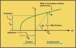
Figure 16. Wall or Surface Yield Locus
(WYL)
The surface friction characteristics are displayed by the
wall yield locus W .Y .L.; the surface friction angle Φ is defined as
follows:
Φ = tan-1 (ﺡ
/ σw)
---------------- (2)
where ﺡ
= shear stress at the wall
σw = corresponding normal stress at the surface.
As indicated by Figure 16, the friction angle Φ
between the bulk solid and boundary surface decreases as the normal
pressure increases. This effect is illustrated in Figure 17.
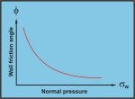
Figure 17. Characteristic Surface or Wall Friction Variation
with Normal Pressure
6.3 Interaction Characteristics
Bulk solid/boundary surface friction and adhesion
depend on the interaction between three groups of variables, those
relating to the bulk solid, those relating to the wall or boundary
surface and those which arise from loading and environmental conditions.
This interaction is shown, diagrammatically in Figure 18.

Figure 18. Bulk Solid/Boundary Surface Friction
Interactions
The relevant properties in each of the three groups
are summarised as follows :
(i) Bulk Solid Characteristics -
(ii) Wall Surface Characteristics -
-
Surface roughness
-
Hardness
-
Chemical composition
(iii) Loading and Environmental Factors -
-
Pressure between bulk solid and wall surface
-
Relative rubbing or sliding velocity
-
Temperature and humidity or moisture conditions
-
Wall vibrations
-
Undisturbed contact time
6.4 Wall Friction versus Normal Pressure
Characteristics
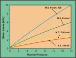
As an illustration of some of the factors influencing
wall or surface friction, a set of wall yield loci graphs are shown in
Figure 19 [20]. The bulk solid in this case is coal. Figure 19(a) shows
the variation of wall friction for black coal at 10% moisture content on
three surfaces, namely, stainless steel type 304 with 2B finish, mild
steel polished and mild steel rusted all at the instantaneous or zero
storage time condition. In the case of the 120 polished mild steel
surface the wall friction was also determined after 72 hours undisturbed
contact or storage time is also shown; the high friction in this case is
quite considerable with corrosion and adhesion or bonding of coal
particles to the steel surface.
Figure 19(b) compares the Wall Yield Loci for black
coal at 19.7% moisture content and brown coal at 65% moisture content on
two surfaces, stainless steel type 304 with 2B finish and Tivar 88, an
ultra high molecular weight polyethylene material. While in absolute
terms the moisture contents of the two coals are significantly
different, in relative terms, taking account of their composition and
saturated moisture conditions, they are comparable. For the black coal
the wall friction angle for stainless steel and Tivar are similar, both
exhibiting low friction. This is also the case for brown coal on the
Tivar surface. However, the brown coal has abnormally high friction on
the stainless steel, despite the smoothness of the surface; the
stainless steel is entirely unsuitable for brown coal.
(a) Wall Yield Loci for Black Coal |

(b) Wall Yield Loci for Black and Coals |
Figure 19. Typical Wall Yield
Loci
6.5 Surface Roughness
(a) Roughness Parameters and Effect on Wall Friction
Surface roughness is an important factor in terms
of its influence on wall friction. Yet the specification of surface
roughness in terms of appropriate parameters which adequately describe
the surface is a complex matter requiring careful and detailed
consideration.
It is common to simplify surface characteristics in
terms of height parameters, such as the centre line arithmetic average
roughness (CLA or Ra Number) or RMS roughness. Such parameters are
useful for comparison purposes but do not adequately provide an
assessment of the interaction between panicle size and surface
profile. For this reason, Ooms and Robens [18] have found it useful to
specify the surface characteristics in terms of Surface Spectoral
Density. This displays the RMS roughness amplitude as a function of
frequency where the frequency is the inverse of the roughness wave
length.
(b) Roughness Classification of Surfaces used in Bulk
Solids Handling
The new Australian Standard on Loads in Bulk Solids
Containers [11] designates four surface roughness characteristics Dl
to D4. In order that these surface classifications may be quantified
in some way, Ooms (Ref. [21]) proposed that the four categories of
surfaces be grouped in terms of roughness bands based on the Mean
Centreline Roughness or Ra number. Surfaces commonly used have been
classified according to this procedure and presented in Figure 20.

Figure 20. Ooms Chan for Lining Surface Roughness
Classification
From the discussion in the previous Section, it is
apparent that the proposed form of classification is somewhat
restrictive in terms of the limited information conveyed by the Ra
number. Also the wall roughness may not necessarily remain constant and
should be considered as a variable. For instance, a polished or lightly
rusted carbon steel surface may become deeply pitted and change from
group D2 to group D3. An aluminium surface is easily scored and may
change from group Dl to group D2. On the other hand, some stainless
steel surfaces will polish during service and may change from group D2
to D 1.
6.5 Influence of Vibrations
Roberts et al [22-24], have shown that the
application of vibrations to a wall surface can significantly reduce
wall friction and therefore promote flow. Vibrations can also reduce
bulk strength, further assisting in promoting gravity flow. The evidence
indicates that the best results are achieved by using frequencies of 100
Hertz or higher, and low amplitude.
7. ADHESION OF BULK SOLIDS ON WALLS OR SURFACES
7. 1 Adhesion of Bulk Solids in Chutes
The characteristics of surface or wall friction
discussed in the previous section indicate that, for most bulk solids
and lining materials, the Wall Yield Loci (WYL) tend to be convex upward
in shape. Furthermore the WYL often intersect the shear stress axis
corresponding to zero normal pressure indicating an adhesion/cohesion
effect as depicted in Figure 18.
Problems due to high wall friction, cohesion and
adhesion, which are associated with low pressure conditions, often occur
in chutes and standpipes. Cohesion and adhesion can cause serious flow
blockage problems when corrosive bonding occurs, such as when moist coal
is in contact with carbon steel surfaces. The bonding action can occur
after relatively short contact times. Impurities such as clay in coal
can also seriously aggravate the behaviour due to adhesion and cohesion.
Transfer chutes should be designed to ensure that
satisfactory flow is obtained without flow blockages. Yet despite their
apparent simplicity, the flow patterns developed in chutes often not
fully appreciated. Occasions have arisen in practice where costly flow
interruptions have occurred due to incorrect chute design arising from a
lack of understanding of the bulk solid and chute surface friction
characteristics.
The design of transfer chutes is discussed in
References [25-28]. Consideration should be given to the flow properties
of the bulk solid and the characteristics of the chute lining material.
Moist coal can adhere to vertical, as well as inclined faces of steel
chutes eventually causing blockages. This has been found to occur in
practice after only a few hours of operation. Problems of this type have
occurred, for example, in conveyor feed chutes in coal screening
operations as illustrated in Figure 21. The momentum of the coal
particles falling from the screen is usually not sufficient to cause
scouring of the chute surfaces and, as a result, build-up and complete
blockages have been known to occur.
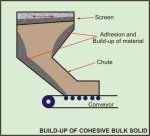
Figure 21. Build-Up of Cohesive Bulk Solid such as Coal on
Screen House Conveyor Feed Chute
When determining chute slope angles, account must be
taken of the variation of friction angle with change in consolidation
pressure, or more particularly, with change in bed depth. Figure 22
shows, for a typical coal, the variation of wall friction angle with bed
depth. As indicated, high friction angles can occur at low bed depths,
the decrease in friction angle being significant as the bed depth
increases.
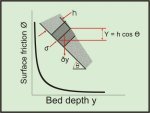
Figure 22 Wall friction angle versus bed depth for bulk
solid on chute
The slope θ of the chute should be at least 5
larger than angle of equivalent friction [4].
That is :
θmin = tan-1 [tanΦ (1 + Kv Ho
/ B)] + 5o
where Φ = Wall friction angle corresponding to HO
Ho = Bed depth
B = Chute width
Kv = Ratio lateral to normal pressure
Kv will depend on bulk solid properties Normally
Kv =
0.5 to 1.0. In the absence of information Kv may be taken to be 0.8.
Often moist bulk solids will adhere initially to a
chute surface, but as the bed depth increases, the corresponding
decrease in friction angle will cause flow to be initiated. In some
cases flow commences with a block-like motion of the bulk solid as
depicted in Figure 23.
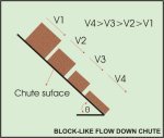
Figure 23 Block-like Flow Down
Chute
7.2 Adhesion in Vertical Chutes or Standpipes
Bulk solids, such as coal with high clay contents and
at high moisture contents, may adhere to walls of vertical pipes or
chutes leading to progressive build-up and flow choking. Problems of
this type have been known to occur in the coal handling plant of power
stations, as depicted schematically in Figure 24.
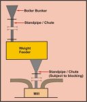
Figure 24 Schematic Arrangement of Coal Handling Plant of
Typical Power Station
When blockages occur in feed-pipes to the feeder and
mill, a boiler may "flame out" in the space of a few minutes.
Blockages are initiated by the coal adhering to the pipe wall and then
growing inwardly, this action often occurring after only a few tonnes of
coal have passed through the system. Often such problems occur when
unwashed coal is stored in open stockpiles prior to use. The weathering
process can cause the clays to be dispersed, rendering them more likely
to adhere to chute and pipe walls. The adhesion process may be
aggravated in this case due to the temperature of the mill and standpipe
above the mill.
It is important that the pipe or chute diameter be
sufficiently large to cause the bulk solid to fall away from the walls.
A proposed simplified methodology is presented. Referring to Figure 25,
assuming the weight of bulk solid is just sufficient to cause slip along
the wall, the required pipe or chute diameter D is given by
D ≥ 4ţ / ŷ (1 - C2 )
------------------ (4)
where :
C = d / D such that C ≥ 0.8
ţ = shear stress at wall corresponding to normal
pressure σ
ŷ = ρ g = bulk specific weight.
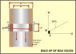
Figure 25 Build-Up of Bulk Solid in Vertical Chute or
Standpipe
It is also wise to check whether the pipe diameter is
sufficient to prevent a cohesive arch forming. For this analysis, the
methods presented in Refs. [3,4] may be used.
8. WEAR IN BULK HANDLING PLANT
Wear in bulk handling plant may result from impact or
abrasion or, as is often the case, a combination of both. In addition,
deterioration of metal surfaces can occur as a result of corrosion.
8.1 Impact
Erosive type wear due to impact consists of a
combination of plastic deformation and cutting wear. Such wear, for
example, occurs in pipe bends of pneumatic conveying systems where
impact velocities are normally relatively high and where several impacts
and rebounds may take place. Normally the particle size is small in this
case.
Impact wear also occurs at discharge points of belt
conveyors and at entry points to transfer chutes. Velocities of impact
are normally relatively low whereas particle size range can be quite
wide with large lumps being present.
Impact wear depends on several factors, the relative
hardness of the particles and the surface having a significant
influence. For impact on hard, brittle materials, the greatest amount of
damage occurs when particles impringe at angles of approximately 90.
On the other hand, for ductile materials, the greatest amount of erosive
wear occurs when particles strike the surface at low angles of attack,
usually in the range 15 to 30. Erosive wear due to impact is
normally composed of two types, deformation wear and cutting wear.
8.2 Abrasive or Rubbing Wear
This occurs in storage bins and silos particularly in
hoppers under mass-flow conditions. Under mass-flow the pressures in a
hopper will vary significantly over the hopper surface, with the maximum
pressure occurring at the transition, the pressure decreasing towards
the outlet. The velocity of the bulk solid adjacent to the wall
increases non-linearly from the transition to the hopper outlet. While
the magnitude of the velocity at particular point on the hopper wall
depends on the bin discharge rate, normally the bulk solid velocities
are quite low with pure sliding taking place.
Abrasive wear also occurs in transfer chutes, the
flow being characterised by lower pressures and higher velocities than
those occurring in hoppers. There are several other areas where abrasive
wear is experienced such as in feeders, belt conveyors, vibratory
conveyors and screw conveyors. Any mechanical device which involves the
motion of bulk solids relative to surfaces will experience wear
problems.
8.3 Abrasive Wear Parameters
The concepts of a non-dimensional Relative Wear
Number NWR has been introduced [20] in order to permit comparisons to be
made between different bin and chute geometries, is defined as :
NWR = [(σw / ŷB) (Vs / Vo) tan Φ
Where :
σw = Normal pressure at boundary
ŷ = Bulk specific weight
B = Characteristic dimension, B = outlet dimension in
case of hopper; B = chute width in case of chute
Vs = Velocity of sliding at wall
Vo = Sliding velocity at reference location.
For hopper, Vo is defined at transition of cylinder and
hopper
For chute, Vo is normally defined at point of entry to chute
Φ = Wall friction angle
8.4 Wear in Mass-Flow Bins
The application of the foregoing to the assessment of
relative wear in mass-flow bins has been discussed in Ref. [20]. By way
of illustration, the relative wear profiles for axi-symmetric (or
conical) and plane-flow bins having the same opening dimension and
hopper half angle respectively are illustrated in Figure 26. In the case
of the axi-symmetric bins, the maximum relative wear occurs at the
outlet, while for the plane-flow bins the maximum relative wear occurs
at the transition. In the latter case the wear at the transition is
likely to be less than as indicated in Figure 26 owing to the possible
build-up of material at the transition. Also, the normal wall pressure
occurring at the transition is difficult to predict precisely and is
likely to be lower than as indicated.
Some bins are constructed with a variable hopper
slope and with the hopper section having different surface textures.
Such a bin is discussed in Ref. [29]. The bin in question is axi-symmetric
with a capacity of 2400 tonnes. The hopper was lined with 3 mm type
304-2B stainless steel. Examination of the lining after approximately 5
million tonnes of coal had passed through the bin showed that the
maximum wear of the stainless steel was around 1mm.
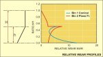
Figure 26 Relative wear profiles for axi-symmetric and
plane-flow mass-flow bins
B = 1.0 m, α = 22, Ф (cylinder) = 30,
Ф (hopper) = 20
8.5 Avoidance of Wear Problems due to Eccentric Funnel-Flow
Serious wear problems will occur during funnel-flow
where the flow channel or pipe is not fully contained in the bulk solid
itself but may incorporate part of the hopper or bin wall. Problems of
this nature may occur when bins with eccentric discharge are used,
particularly when the bin opening is located near aside wall. On other
occasions a badly designed feeder may cause material to pipe adjacent to
the hopper wall. Flow channels of this nature give rise to high velocity
flow against the wall resulting in accelerated wear.
Often side delivery chutes are incorporated in bins
for the purpose of off-loading bulk materials. Side delivery chutes
create undesirable flow patterns in bins, leading to accelerated wear of
the bin wall in the region of the chute intake as well as in the plates
above the chute. This wear is caused by both abrasion and impact
Abrasive wear results from the high velocity of the materials during
chute discharge, the flow velocity of the materials during chute
discharge, the flow following a funnel-flow pattern, as Indicated in
Figure 27. The eccentric discharge induces a non-uniform pressure
distribution, as shown; bending is induced and the bin shell is deformed
as indicated by the dotted curve.
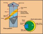
Figure 27 Eccentric discharge due to use of side delivery
chutes
Impact wear can occur on filling the bin after
discharging from the side delivery chute. The surface is left in a
rilled condition as indicated in Figure 27. When filling commences,
lumps of bulk material may bounce off the rilled surface and impact the
wall in the weakened area above the chute.
It should be noted that despite the fact that side
delivery chutes may only be used intermittently, the wear rate during
operation is considerable. It is therefore most desirable that side
delivery chutes be avoided and incorporate any off-loading via a
transfer conveyor operating from the main bin discharge. If side
delivery chutes are used, such as an existing installation, it is
essential that the bins be lined with wear plates in the region of the
chute intakes as well as above the chutes.
8.6 Wear in Transfer Chutes
Abrasive wear in transfer chutes has been discussed
in Ref. [18-21]. In the case of straight inclined chutes of constant
cross-sectional geometry, the wear is constant along the chute. For
chutes of constant curvature, it has been shown that the wear varies
along the chute as depicted in Figure 28 reaching a maximum at a
particular chute angle and then decreasing. However, the wear is
virtually independent of chute radius.
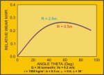
Figure 28. Wear factor for circular curve chutes [20]
Q = 30 tonnes/hr, Vo = 0.2 m/s, ρ= 1000 kg/m3, b =
0.5 m, E = 0.6, Ф = 30.
8.8 Abrasive Wear Tests
In order to evaluate lining materials for wear
resistance, a linear wear tester, as proposed by Roberts [30,31], has
been developed jointly at The University of Twente, The Netherlands, and
The University of Newcastle, Australia. The tester, which is shown in
Figure 29, incorporates the following features:
- Provision for a continuous supply of
"fresh" bulk solid.
- Provision for the bulk solid normal pressure
on the test surface to be varied over the specific range.
- Provision for the sliding or rubbing velocity to
be varied over the specific range.
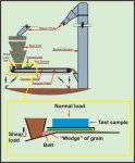
Figure 29. Abrasive Wear Tester
During tests, the friction
coefficient, surface roughness, weight and thickness loss are progressively
monitored. The teat samples used in the linear wear tests are of similar size to
those used in the Jenike Direct Shear Test. This allows cross checking of the
wall or boundary friction at various stages throughout the tests. A typical set
of test results are illustrated in figure 30.

Figure 30. Comparative Wear Rates for Three Common Lining
Materials
9. PULSATING LOADS IN BINS -'SILO QUAKING'
9.1 General Discussion
As is often the case, the solution of one problem
which leads to an improvement in plant performance exposes other
problems which require further research and development, This applies
particularly to gravity flow in storage bins and silos where the
application of known theories for reliable discharge, such as by
mass-flow, can give rise to dynamic or pulsating flow effects. These
effects are normally imperceptible as far as bin discharge is concerned
having no detrimental effect on the plant operation. However, the
pulsating flow can have a significant influence on the loads acting on
bin walls by imposing severe dynamic loads. The phenomenon is often
described as 'silo quaking'; it may be linked with the critical head Hcr
for mass-flow as discussed in Section 2.
The discussion that follows provides a qualitative
view of the 'silo quaking' problem as it r relates to mass-flow,
funnel-flow and expanded-flow bins.

(a) Velocity Profiles and Pressure Distribution (b)
Variable Density and Dilation
Figure 31 Mass-Flow Bin
Referring to the mass-flow bin depicted in Figure 31;
as the material flows, it dilates leading to variations in density from
the static condition. This is depicted pictorially in Figure 31(b). With
H > Hcr, the flow in the cylinder is uniform or 'plug-like' over the
cross-section, with flow along the walls. In the region of the
transition, the flow starts to converge due to the influence of the
hopper and the velocity profile is no longer uniform. The velocity
profile is further developed in the hopper as shown. As the flow
pressures generate in the hopper the further dilation of the bulk solid
occurs. As a result of the dilation, it is possible that the vertical
supporting pressures decrease slightly reducing the support given to the
plug of bulk solid in the cylinder. This causes the plug to drop
momentarily giving rise to a load pulse. The cycle is then repeated.
Studies of the phenomenon of pulsating loads in bins
and silos are presently in progress at the University of Newcastle,
Australia. In this work, a pilot scale mass-flow, steel silo 1.2m
diameter by 3.5 m high and fitted with a stainless steel hopper is being
used. The silo is fitted with 14 load cells designed by Prof. V.
Askegaard of the Technical University of Denmark; these cells are
capable of measuring both normal pressure and wall shear stress. An
example of a wall pressure and shear stress records depicting the
pulsating load in the cylinder are shown in Figure 32.

Figure 32. Load Cell Records depicting Pulsating
Loads in Mass-Flow Bin
A similar action to that described above for
mass-flow bins may occur in tall funnel-flow bins or silos where the
effective transition intersects the wall in the lower region of the
silo. As a result, there is flow along the walls of a substantial mass
of bulk solid above the effective transition.
During funnel-flow in bins of squat proportions,
where there is no flow along the walls, as depicted in Figure 33,
dilation of the bulk solid occurs as it expands in the flow channel. As
a result some reduction in the radial support given to the stationary
material may occur. If the hopper is fairly steeply sloped, say [θ
≥ δ], then the stationary mass may slip momentarily causing
the pressure in the flow channel to increase as a result of the
'squeezing' action. The cycle then repeats.
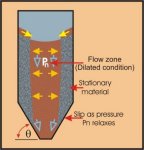
Figure 33 Funnel Flow Bin
A similar behaviour may occur in expanded flow bins,
such as the bin depicted in Figure 2 .Pulsating loads can occur in such
bins, particularly if the slope angle e of the transition is too steep.
Owing to segregation on filling, larger size particles are more likely
to be located adjacent to the sloping surface at the lower end of the
funnel-flow section. Such particles tend to roll as well as slide,
aggravating the load slipping problem and giving rise to load
pulsations. Problems of this type have been experienced in large coal
bins.
7.2 Multi-Outlet Coal Bins
Silo-quaking problems have been known to occur in
bins with multiple outlets. By way of illustration, consider the large
coal bin shown in Figure 34. The bin has seven outlets, six around an
outer pitch circle and one located centrally. The hopper geometries
provide for reliable flow permitting complete discharge of the bin
contents. Coal was discharged by means of seven vibratory feeders onto a
centrally located conveyor belt. When the bin was full or near full,
severe shock loads were observed at approximately 3 second intervals
during discharge. The discharge rate from each feeder was in the order
of 300 t/h. When the level in the bin had dropped to approximately half
the height, the shock loads had diminished significantly. With all the
outlets operating, the effective transition was well

Figure 34 Multi-Outlet Coal Bin
down towards the bottom of the bin walls and the critical
head Hm was of the same order as the bin diameter and greater than DF.
Substantial flow occurred along the walls, and since the reclaim hoppers
were at a critical slope for mass and funnel-flow as determined by flow
property tests, the conditions were right for severe 'silo quaking' to
occur.
Confirmation of the mechanism of silo quaking was
obtained in field trials conducted on the bin. In one series of tests the three feeders along
the centre line parallel with the reclaim conveyor were operated, while the
four outer feeders were not operated. This induced funnel-flow in a
wedged-shaped pattern as indicated in Figure 34, with the effective
transition occurring well up the bin walls, that is Hm < Hcr
(= DF ) or Hm << D. The same was true when only the central feeder (Fdr. 1) was
operated; in this case the stationary material in the bin formed a conical
shape. Under these conditions, the motion down the walls was greatly
restricted and, as a result, the load pulsations were barely perceptible.
In a second set of trials, the three central feeders were
left stationary, while the four outer feeders were operated. This gave rise
to the triangular prism shaped dead region in the central region, with
substantial mass-flow along the walls. The load pulsations were just as
severe in this case as was the case with all feeders operating. Dynamic
strain measurements were made using strain gauges mounted on selected
support columns. When the bin was full (or near full), the measured dynamic
strains with Hm Hcr were in the order of 4 times the strains measured
when the flow pattern was controlled so that Hm < Hcr.
10. CONCLUDING REMARKS
In this paper an overview of some salient aspects of the
storage, flow and handling of bulk solids has been presented. It is quite
clear that, in recent years, significant advances have been made in research
and development associated with bulk handling systems. It is gratifying to
acknowledge the increasing industrial awareness and acceptance throughout
the world and particularly in Australia of modern bulk materials handling
testing and plant design procedures. These procedures are now well proven,
and while much of the industrial development has, and still is, centred
around remedial action to correct unsatisfactory design features of existing
systems, it is heartening that in many new industrial operations the
appropriate design analysis and assessment is being performed prior to plant
construction and installation. It is most important that this trend
continues.
The paper has indicated, by way of example, the ongoing
need for research and development which is necessary as industrial plant and
processes become more sophisticated, the demands for better quality control
become more stringent and both national and international competition
requires more efficient and cost-effective performance.
11. ACKNOWLEDGEMENTS
Much of the work presented in this paper is based on a
current research grant from AMIRA. The support of AMIRA and the sponsoring
companies is gratefully acknowledged.
REFERENCES
- Jenike, A.W. "Gravity Flow of Bulk Solids".
Bul. 108, The Univ. of Utah, Engn Exp. Station, USA 1961.
- Jenike, A.W. "Storage and Flow of Solids". Bul.
123, The Univ. of Utah, Engn Exp. Station, USA 1964.
- Arnold, P.C., McLean, A.G. and Roberts, A.W. "Bulk
Solids: Storage, Flow and Handling". The University of Newcastie Research
Associates (TUNRA), Australia, 1982.
- Roberts, A. W ."Modern Concepts in the Design and
Engineering of Bulk Solids Handling Systems". TUNRA Bulk Solids Research, The
University of Newcastle, Australia, 1988.
- Thomson F.M. "Storage of Particulate Solids".
Chapter 9, Handbook on Powder Science & Technology. (1984) Van Nostrand.
- Jenike, A.W. "A Theory of Flow of Particulate Solids
in Converging and Diverging Channels Based on a Conical Yield Function". Powder
Tech., Vol.50. (pp. 229-236).
- Benink, E.J. "Flow and Stress Analysis of
Cohesionless Bulk Materials in Silos Related to Codes". Doctoral Thesis, The University of
Twente, Enschede, The Netherlands. 1989.
- Roberts, A.W. and Ooms, M. "Wall Loads in Large Steel
and Concrete Bins and Silos due to Eccentric Draw-Down and Other Factors".
Proc. 2nd Inti. Conference on 'Design of Silos for Strength and Flow',
Powder Advisory Centre, U.K., 1983, (ppI51-170).
- Ooms, M. and Roberts, A. W ."The Reduction and
Control of Flow Pressures in Cracked Grain Silos". Bulk Solids Handling, Vol. 5,
No.5, Oct. 1985. (pp.1009-1016).
- Roberts, A. W. "Some Aspects of Grain Silo Wall
Pressure Research -Influence of Moisture Content on Loads Generated and
Control of Pressures in Tall Multi-Outiet Silos". Proc. 13th Inti.
Powder and Bulk Solids Conf., Chicago, USA, May 1988. (pp.II-24).
- Australian Standard AS89138 "Loads on Bulk Solids
Containers"
- Roberts A. W ., Ooms M and Manjunath K.S., "Feeder
Loads- and Power Requirements in the Controlled Gravity Flow of Bulk Solids
from Mass-Flow Bins" Trans. I.E.Aust., Mechanical Engineering, V.ME9, No.1, April
1984.
- Manjunath,K.S. and Roberts, A.W., 'tWall Pressure-Feeder
Load Interactions in Mass-Flow Hopper/Feeder Combinations". Part I. IntI.
Jnl. of Bulk Solids Handling, Vol. 6, No.4, Aug. 1986.
- Manjunath, K.S. and Roberts, A.W., "Wall
Pressure-Feeder Load Interactions in Mass-Flow Hopper/Feeder Combinations". Part II. Inti.
Jnl. of Bulk Solids Handling, Vol. 6, No.5, Oct. 1986.
- Rademacher, F.J.C., "Reclaim Power and Geometry of
Bin Interfaces in Belt and Apron Feeders". IntI. Jnl. of Bulk Solids Handling, Vol.
2, No.2, June 1982.
- Roberts, A. W. and Teo, L.H., "Performance
Characteristics of Gravity Reclaim Stockpiles of Conical Form", Trans. of Mechanical
Engineering, The Instn. of Engrs. Australia, Vol. ME 14, No.2, 1989, pp.97-102.
- Roberts, A. W .and Teo, L.H., "Design Considerations
for Maximum Reclaim Capacity of Conical Stockpiles", IntI. Journal of Bulk
Solids Handling, Vol. 10, No. 1, 1990.
- Ooms, M. and Robens, A.W. "Significant Influence of
Wall Friction in the Gravity Flow of Bulk Solids". IntI. Jnl. of Bulk Solids
Handling, Vol. 5, No.6, 1985 (pp.1271-1277)
- Robens, A.W., Ooms, M. and Scott, O.J. "Surface
Friction and Wear in the Storage, Gravity Flow and Handling of Bulk Solids".
Proc. Conf. 'War on Wear', Wear in the Mining and Mineral Extraction Industry, Instn. of
Mech. Engnrs, Nottingham U.K., 1984. (pp.123-134).
- Robens, A. W. "Friction, Adhesion and Wear in Bulk
Materials Handling". Proc., AntiWear 88, The Royal Soc. London. 1988. Inst. of Metals,
I.Mech. E. .
- Roberts. A.W., Ooms, M. and Wiche, S.J. "Concepts of
Boundary Friction, Adhesion and Wear in Bulk Solids Handling Operations".
IntI. Jnl. of Bulk Solids Handling, Vol.10, No.2, May 1988. :
- Robens, A.W."Vibrations of Powders and Bulk
Solids". Chapter 6, Handbook on Powder Science & Technology. (1984) Van
Nostrand.
- Robens, A.W., Ooms, M. and Scott, O.1. "Influence of
Vibrations on the Strength and Boundary Friction Characteristics of Bulk Solids and
the Effect on Bin Design". Inti. Jnl. of Bulk Solids Handling, Vol.6,
No.1. 1986. (pp.161-169).
- Robens, A.W. and Rademacher, F.J.C. "Induced Gravity
Flow by Mechanical Vibrations". To appear in Inti. Jnl. of Bulk Solids
Storage in Silos, UK.
- Robens A. W. "An Investigation into the Gravity Flow
of Non-Cohesive Granular Materials Through Discharge Chutes". Trans. A.S.M.E.,
Jnl. for Engng. in ,Industry, Vol. 91, Series B, No.2, May 1969. (pp. 373-381). ,
- Robens A. W. and Scott O.1. "Flow of Bulk Solids
Through Transfer Chutes of J Variable Geometry and Profile". Bulk Solids Handling,
Vol. 1, No.4, December 1 1981. (pp. 715-727).
- Parbery , R.D. and Robens, A. W ."On Equivalent
Friction for Accelerated Gravity 1 Flow of Granular Materials in
Chutes". Powder Technology, Vol. 48. 1986. (pp. 75-79). ;
- Savage, S.B. "Gravity Flow of Cohesionless Granular
Materials in Chute and Channels". J.Fluid Mech. Vol.92, Pan 1, 1979.
(pp.53-96).
- Andrews, B.R., Boundy, B .1. and Roberts, A. W .,
"Flow Property Analysis, Design and Construction Details for a 2400 tonne Mass-Flow
Bin". IntI. 1nl. of Bulk Solids Handling, Vol. 3, No.4, November 1983.
(pp.781-786).
- Roberts, A. W., " Abrasive Wear Testing and Analysis
in Bulk Solids Handling", Report of Bulk Solids Research Group (Sectie
Stort-geotechnologie), Dept. of Mechanical Engineering, University of Twente, The
Netherlands, 1986.
- Roberts, A.W., "Hopper and Chute Performance and
Wear", AMIRA Project No. 245, Handling of Bulk Solids, The University of Newcastle,
1989.
- Roberts, A. W., Ooms, M., Askegaard, V. and Wiche, S.1.
"Investigation of Flow Instabilities and Beating in Silos'. Paper for
Presentation at the cmsA 90 Congress, Prague, Czechoslovakia. August 1990.