Courtesy : Trans Tech Publications - Bulk Solids Handling Journal
1. Introduction
On 13.08.92 Sasol 2 selected Sasol Coal's Project and Research Services Department as the main contractor for the 10.7 million dollar contract for the upgrading of the coal conveyor systems in its plant.
Sasol is the world leader in the conversion of coal to gas, synthetic fuels and chemicals. Sasol 2 and 3, located at Secunda in the south-eastern Transvaal, are its largest plants - successors to the original Sasol 1 plant at Sasolburg in the Orange Free State.
The two Secunda plants are supplied with coal by Sasol Coal's Brandspruit, Middelburg and Bosjesspruit underground collieries at Secunda and the nearby Syferfontein strip mine, together producing a total 33 mt/a. The underground complex is the largest underground coal mining complex in the world.
Coal for Sasol 2 is blended on three stockpiles, each equipped with a drum reclaimer delivering coal to belt conveyor systems feeding the plant and subsequently to the bunkers above the wet screening plant of Sasol 2 and from here to the primary screens. From the first and second decks of these screens coal -100 +6.3 mm is loaded on to conveyors 3 and 4 (Figs. 1 and 2) whilst coal -6.3 mm is sent to secondary screens and subsequently the fraction -6.3 +4.5 mm is loaded onto conveyors 6 and 7 and fraction -4.5 mm is sent to the steam plant via centrifuges and conveyors 9, 10, 11, 12.
It is also possible to send coal -6.3 +4,5 mm from the individual screens to the steam plant. In total, less than 30% of coal goes to the steam plant whilst more than 70% via conveyors 15, 15a, 16 and 17 (previously only 15,16, and 17), Structure Four, conveyors 18, 19, 20 and 21 to the gasification plant consisting of 40 gasifiers grouped in four wings.
The existing conveyor systems had been designed in the mid-Seventies when the Sasol 2 and 3 plants were built and had only undergone minor modifications since then.
2. Problem Definition
In June 1991 the Project and Research Services Department was approached by Sasol 2 management to assist in its investigation into coal degradation occurring on the route between the primary screens of wet screening plant and bunkers above gasifiers in the gasification plant, apparently causing serious operating problems and limiting the capacity of the gasification plant.
A holistic approach was followed in the investigation. All relevant information and, in particular, various test reports were gathered and analysed by Project and Research Services. A test programme was designed and implemented according to ISO Standard 1988-1975E. As a result a variety of problem areas were identified, including the following:
-
Segregation, which was found to be the major contributor towards gasifier operating problems.
-
Degradation, which was seen as secondary to segregation but still a major area of concern.
-
Blending.
It was decided that instead of studying degradation in isolation, the aspects of segregation and blending should also be investigated and subsequently they were found to be major contributors to the problems of gasifiers.
2.1 Segregation
Three areas were found to be the root cause of the problem:
-
Structure four, where the coal flow from conveyors 15, 16 and 17 was segregated as a result of the direction in which the splitting of coal took place in chutes.
-
At the transfer points from conveyors 18, 19, 20 and 21 for the same reason as above (Fig. 3).
-
Bunkers above gasifiers where the funnel type coal flow takes place.
2.2 Degradation
The following most significant problem areas were identified:
-
Chutes. Coal was transferred down through a chute network of a total height of approximately 28 m.
-
Design of chutes as in some places the speed of coal particles was very high.
2.3 Blending
The fine coal (-6.3 +4.5 mm) was delivered from conveyors 6 and 7 onto conveyors 16 and 17 whilst the coarse coal (- 100 +6.3 mm) from conveyors 3 and 4 onto 15, 16 and 17. It obviously created the situation where some of the gasifiers were supplied only with the coarse coal whilst the others were supplied with an excess of fines. Moreover, the amount of fines delivered to conveyors 16 and 17 was not in proportion to the amount of coarse coal they received from conveyors 3 and 4 as there was no control system to regulate the mix between these two flows of coal.
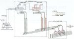
Fig. 1: Coal flow diagram: wet screening plant - Structure Four (before up-grading)
3. Objective of the Project
After these problem areas had been identified and consultations with Sasol 2 and Sasol 3 management had been held, the objective for this project could be defined as:
"To provide an identical blend of coal to every gasifier on a continuous basis", with the specific requirements being:
-
To engineer out segregation.
-
To reduce degradation of coal by a minimum of 40%.
-
To provide a blending system.
4. Proposed Solutions
To analyse the solutions presented below one has to have in mind that Sasol 2 consumes approximately 46,000 t of coal a day. These enormous quantities precluded the use of provisional systems and methods. Most of installed equipment had to be right the first time.
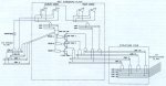
Fig. 2: Coal flow diagram: Wet screening plant - Structure Four (after up-grading)
4.1 Segregation
To solve the segregation problem a change in the plant operating philosophy was proposed. Instead of having full flexibility from 0 to 100% in Dividing the flow of coal in the chutes it was decided to allow for only three possibilities namely: 0 100%, 50 - 50%, 100 - 0%. The only one which could create a problem was the 50 - 50% split, but by changing the direction in which coal is split from horizontal to vertical the problem would be practically eliminated. All chutes where segregation previously took place, were subsequently re-designed accordingly.
In the initial stage of the project the modification to bunkers above the gasifiers to provide mass flow of coal was considered. For test purposes one bunker was modified but eventually, after detailed analysis, this part of the project was cancelled.
4.2 Degradation
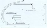
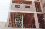
The main improvement regarding degradation was achieved by lifting tail-ends of conveyors 15, 15a, 16 and 17 in the wet screening plant as well as 18, 19, 20 and 21 in Structure Four. It resulted in reduction of approximately 14 m in the total transfer height for any coal trajectory. In Fig. 4 the new structure for conveyors 15 and 15a can be seen as well as old conveyors 16 and 17. The transfer height reduction of 5,7 m in the wet screening plant is clearly visible.
For further improvement, all chutes were designed in such a way that the impact of coal against the chute is kept as low as possible and the speed of coal particles leaving the chute is as close as practically possible to the speed of the recieving belt.
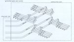
Fig. 3: Coal flow diagram: Structure Four - gasification plant
4.3 Blending
The solution to this problem could be described as providing an identical proportion between coarse coal (-100 + 6.3 mm) and fines (-6.3 + 4.5 mm) on belt conveyors 15, 15a, 16 and 17 irrespective of the number of belt conveyors in operation and the amount of coal being loaded onto those conveyors.
To comply with these requirements the blending system was designed. It comprises: coarse coal belt conveyors 3 and 4, a fine coal bin with the overflow system, three chain feeders controlling outlets from the bin, three C-loop conveyors, conveyors 15, 15a, 16 and 17 and various measuring and controlling instruments.
Fine coal from the first and second deck of secondary screens is delivered by belt conveyors 6 and 7 to the fine coal bin. The amount of coal in the bin is measured by four load cells from which signals are sent to the control room, enabling operators to regulate the proportion of fine coal demanded by gasification or sent to the steam plant.
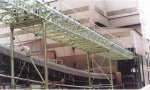
Fig. 4: New structure for conveyors 15 and 15a; old structure for conveyors 16 and 17
5. Why C-Loop Conveyors?
During investigations in 1991 it became clear that to solve the degradation problem it would be necessary, among other possible measures, to significantly decrease the transfer height, between conveyors 3 & 4 and 15, 15a, 16 & 17. This could be achieved only if a method to elevate fine coal from the feeders of the fine coal bin to conveyors 15, 15a, 16 & 17 above, could be found.
Generally, two approaches were possible: either using the conventional approximately 150 inclined belt conveyors or specially designed conveyors with a very high conveying angle, preferably vertical due to serious space restrictions.
The introduction of C-loop conveyors came under consideration as a solution because the coal had to be raised approximately 13 m within an extremely confined area. The space constraint precluded use of a conventional conveyor configuration. The C-conveyor, already proven in applications in the US and Canada as a means of lifting material on a conveyor system from one level to another, appeared to offer the most viable solution.
But although it looked like an attractive solution to our particular problem, we could not afford to take undue risks, taking into account the relative newness of the technology. Consequently, a thorough investigation was carried out which involved suppliers as well as users of C-loop conveyors in North America. Eventually C-loop conveyors were accepted with the basic parameters as follows: