Courtesy : Trans Tech Publications - Bulk Solids Handling Journal
1. Introduction
Belt conveyors with horizontal curves have been successfully used for some years, as demonstrated by a variety of existing plants. The belt conveyors in the Power Station Plant Soma, Turkey, (Fig. 1) with a length of 8.5 km, and the 6 km long belt conveyor in the Optimum Coal Mine, South Africa [3], are mentioned as examples. Plans to use conventionally designed belt conveyor systems for ever narrower curves require that basic calculation principles used in the past should now be critically analysed, and that other factors, which were insufficiently considered in the past, should now be taken into account.

Belt conveyor in Soma Power Plant complex [2]
2. Present Status
The development of the theoretical principles for the design of belt conveyors over the course of time can be derived from [5]. Published research up to now has mainly investigated the influence of
-
a. radiaily acting force components FGB from deadweight of the belt GB and its troughability,
-
radially acting force components FGG from dead-weight of the material GG and
-
radially acting components FR from friction force by tilted carrying idlers on the position of the conveyor belt in the horizontal curved (Fig. 2). These forces, with an admissible off-centre belt run, are required to be in balance with the force FT obtained from the belt tension force T acting radial to the inner side of the curve.
FT = FGB + FGG + FR (1)

Fig. 2: Cross-section through a belt conveyor in a horizontal curve, forces and geometry
Fig. 3 shows the basic model for calculation of the radial force resulting from the belt tension force with
FT = T * IT / R (2)
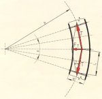
Fig. 3: Top view of a belt conveyor in a horizontal curve, forces and geometry
where T is the belt tension force in the relevant section of the belt, IT the spacing between the carrying idlers and R the radius of the horizontal curve. Past evaluations did not consider that the radial force FT at the troughed belt has to be split, analogously to the weight forces GB and GG, into components vertical and parallel to the carrying idlers to properly determine the effect of this force on the position of the belt.
As far as the normally used horizontal curve radii of conventionally designed belt conveyors is concerned, an approximate approach can be set up assuming the belt tension force T to be uniformly distributed over the total belt cross-section (Fig. 4). As a consequence thereof, the radial force share ΔFT is in proportion to the width of the belt section in contact with the carrying idlers of the belt trough.
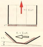
Fig. 4: Distribution of the belt tension force T and the radial force FT in a horizontal curve over the belt cross-section
The following calculation equations are obtained for the components of the radial force FT1 , FTM and FT2 (Fig. 5)
FT1 |
SB1 |
* FT |
(3) |
B |
|||
FTM |
IM |
* FT |
(4) |
B |
|||
FT2 |
SB2 |
* FT |
(5) |
B |
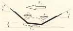
Fig. 5: Model fro distribution of te radial force FT to individual sections of the belt cross-section
where SB1 and SB2 represent the length of the outer carrying idlers in contact with the belt and IM the length of the center carring idler. The components
FTN1 = FT1 * sin(λ + γ) (6)
FTNM = FTM * sinγ
(7)
FTN2 = FT2 * sin(λ - γ) (8)
are acting vertically to the shell surface of the carrying idlers and have to be considered for determination of the friction forces of tilted idlers.
The radial force components
FTT1 = FT1 * cos(λ + γ) (9)
FTTM = FTM * cosγ
(10)
FTT2 = FT2 * cos(λ - γ) (11)
act parallel to the carrying idlers and have a direct influence on the position of the belt. Thereby it was considered that the forces parallel to the carrying idlers follow the direction of the belt trough in the case of commonly used troughing angles, this being a consequence of the transverse stiffness of the belt in the transition area between two adjacent carrying idlers. This was supported by experimental investigations [1]
Thus, with FTT as sum of the components of FT acting parallel to the carrying idlers,
FTT = FTT1 + FTTM + FTT2 (12)
the following equation is valid to determine the off-centre belt run
FTT = FGB + FGG + FR (13)
Since |FTT| < |FT| is valid for a troughed belt, it becomes obvious that past calculation principles started from too high forces acting towards the inner curve. According to [5] the following equation is valid for the determination of FGB and FGG