|
Installation of Vibrating Equipment |
|
J. Stewart, Australia
Courtesy : Trans Tech Publications - Bulk Solids Handling Journal
1. Introduction
Vibration in the workplace can be one of the most disturbing occurrences, and at the same time the least considered of the various pollutants that intrude on our comfort in the workplace, be it factory, mill or office.
Three major items of equipment are responsible for the generation of vibration, and all include some rotating out of balance force which is responsible for the vibration produced: screens, crushers, reciprocating machinery, engines, etc.
Particular items designed to produce vibration, and which rely on vibratory motion for their successful operation are vibrating screens and feeders such as Lockers, Syntron, Linkbelt, etc.
Sizes range from less than 1,000 mm long x 600 mm wide to 6 m x 2.4 m wide, with their frequency ranging from some 700 to 1,500 rpm or about 12 to 25 Hz with masses ranging from 200 kg to more than 2,000 kg.
At lower frequencies are the gyratory crushers at around 4 to 8 Hz. Out of balance forces are much higher than those of the vibrating screens. While these are not designed with a view to producing vibration, the rotation of an out of balance rotor to give the crushing force ensures that vibration is inherent in their operation.
Reciprocating machinery, e.g. compressors, and engines ranging commonly from 1 to 16 cylinders in line or V-configuration. While 3 or 5 cylinder engines may achieve perfect harmonic balance, generally perfect balance can only be achieved in one but not both planes without some expensive additions to the rotating mass of the crankshaft. The compromise is to accept some out balance force in both planes.
The problem in vibration is to contain or limit the amplitude of such vibration within some arbitrary limits set by stress, noise, personal comfort or other factors such as say, damage or life of equipment.
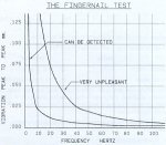
2. Range of Amplitude Vibration
Fig. 1 illustrates the range against which the engineer is pitted an amplitude vibration of 100 m at 3 Hz can be felt, but, at 15 Hz can cause some alarm, where as it takes 25 m at 10 Hz before discomfort is reached and a strong desire may be felt to be elsewhere. The problem for the engineer is to design a supporting structure that is suitably sized and constructed to withstand the impressed vibrating forces.
In selecting a member size the first step is to check its natual frequency.
3. Calculation
3.1 Vibrating Screen or Engine Base
For a vibrating screen, or engine base, the beam support is the primary element and Lord RAYLEIGH in his treatise "Theory of Sound" published in the 1880s, laid down the ground rules for the analysis of vibration.
Consider a beam with a moment of inertia I, of length L, simply supported over a span L. If a load is suddenly applied and removed i.e., an impact load, the beam equilibrium is disturbed and the beam will vibrate. This vibration, maintained by the elastic forces of the beam's internal energy may be described as the natural vibration of the member at its natural frequency.
The frequency depends on the system inertia and the stiffness of the elastic constraints, with the amplitude dependent on the magnitude of the primary impact load.
In his "Theory of Sound" RAYLEIGH noted that for a rod freely vibrating transversely, different assumptions as to the shape of the deflection curve made little difference in the calculated frequency of vibration. Any form of curve assumed gave a larger value of frequency than that found from the use of the true deflection curve, so that results obtained from using an incorrect deflection curve are always conservative.
This allows a simplification to be made in deriving the few equations we really need to solve.
For a beam supporting a uniformly distributed load W the deflection at the midpoint of span L is given by
Where E = YOUNG's modulus, and I = second moment inertia and for the deflection of a beam supporting a load at a point distant x from a support on a span L the deflection is given by
where W = total distributed load, and P = point load.
By equating strain energy to kinetic energy, it is possible to reduce the equations for time, i.e. frequency and displacement to a very simple form.
For a simply supported beam with a distributed load the natural frequency is given by
where Q = square root of midspan deflection in mm or
where S = square root of midspan deflection in inches. For beams with fixed ends
n = 3.58/S Hz (4a)
where Q and S have the same meanings as before.
It will be noted that if we compare these results.
Metric |
Imperial |
|
| Simple beam | 17.72 |
3.517 Hz (Eqs. 3 and 3a) |
| Fixed beam | 18.0 |
3.58 Hz (Eqs. 4 and 4a) |
the differences are quite insignificant, and we can treat all beams as simply supported when selecting members to support vibrating equipment and be certain that our results are always conservative.
Since in supporting equipment there is a system to consider, we have
-
simply supported beam of weight
W = wL, where w = weight or mass per unit length. -
one or more point loads applied non symmetrically about the beam mid point.
Frequencies calculated for each case will vary and to combine these we resort to DUNKERLEY'S formula, analogous to the electrical sum of resistances in parallel, i.e.
We now have the armoury to tackle our vibration problem and to demonstrate, consider the following example.
Example
Consider a vibrating screen, operating at 900 rpm (15 Hz), weight = 2,500 kg, supported on 4 springs at 175 N/mm, angle of slope = 150, stroke = 10 mm (measured perpendicular to the screen), vertical components = 10 cos 15 = 9.659 mm 4.829 mm.
Assume beam = 410 UB60, W = 6 X 60 = 360 kg = 3.538 KN.
Length of beam = 6 m; supported at both ends (a and e); load b at position 1.75 m from a; c positioned at mid point; load d at position 1.25 m from e.
-
Deflection at mid span c from Eq. (1)
d = 5 (3.538) x 10 x (6000)= 0.234 mm 384 x E x 215 x 106and n = 36.63 Hz.
Point load per beam of two beams
= 2,500 x 9.8/(4 x 103) = 6.125 KN -
Substituting in Eq. (2) for load at b
d = 6.125 x 10 x (1750) x (4250)= 0.4377 mm 3 x 2 x 105 x 215 x 106 x 6000and n = 26.78 Hz
-
For load at d
d = 6.125 x 10 x (4750) x (1500)= 0.402 mm 3 x 2 x 105 x 215 x 106 x 6000and n = 27.95 Hz.
[Note that b. and c. assume direct connection to the beam].
To combine - we have from Eq. (5)
1=1+1+1N(36.63)(26.78)(27.95)and N = 17.1.
This is quite close to the actual screen frequency of 15 Hz.
Now consider the screen mounted on springs with a spring rate of 175 n/mm.
Then the impressed force = 175 4.829 = 845 N, and for b. d = 0.4377 x 845/6125 = 0.0638 and n = 70.15 and similarly for c. d = 0.05546 and n = 75.24.
Using DUNKERLEY'S formula Eq. (5) as before, we solve for the system frequency, N = 29.81 Hz. This gives a system/impressed frequency ratio of 29.81/15 = 1.987 or less than 2.
This example highlights the advantage in using spring mountings.
The frequency of 29.81 or 1.987 times the calculated frequency, is just beyond the limits generally used. Based on practical experience and further modified by the beam support, the ratios suggested are as follows:
Connected to column
-
span < 4.8 m = 1.5 x min.
span > 4.8 m = 2 x min.
Beam supported by another beam
-
span < 4.8 m = 2 x min.
span > 4.8 m = 2.5 x min.
Since our span is greater than 4.8 m the ratio of 1.987 is not acceptable and a larger beam is required.
For a 460 UB67 where I = 294 x 106
| d = 0.191; | n = 40.53 |
| d = 0.04666; | n = 82.0 |
| d = 6.04054; | n = 88.0 |
It would require a minor addition to the weight supported by the beam to depress the final effective beam frequency and to cater for this a better solution is to select a larger section 46OUB 74 - additional weight of 7 kg/m = 84 kg.
The sample screen is inclined at an angle of 15 and this means that there is a horizontal component to be considered.
With the beam supported on columns at each end, bracing is best used to control the horizontal components of the motion as the force to be restrained.
If a portal frame is to be used, design for a horizontal deflection in the second decimal place, i.e. a figure of 0.05 mm at the top of a 3 m column will serve as a guide, or 1/60,000 of the column length.
3.2 Gyratory Crusher
This type of crusher is usually fed by bin or V trough conveyor, and consists of a fixed bowl inside which an offset rotating mass revolves about a vertical axis. The centre of gravity of the rotor is commonly 0.800 m to 1 m above the base.
The result is a device, base mounted, of some 1.2 to 1.5 m which has to be mounted above some form of conveyor, since the discharge is through the bottom of the machine, so that the crusher base will be some 2 to 3 m above the ground or floor line to accommodate the crusher output discharge conveyor system.
The supporting structure therefore is subjected to a horizontal force equal to the rotor weight and operating at the rotor speed. In addition, due to the height of the centre of gravity of the rotor above the crusher base a rocking moment also acts and applies a vertical force to the mounting beams, acting simultaneously with the horizontal force.
Typical rotational speeds are 300 ... 400 rpm with a weight of 4 t or more, with an out of balance rotor weight being around 1 t.
As an example consider the following data
| Gyratory crusher | |
| Weight | 4.4 t |
| Rpm | 370 |
| Base | 1.2 m |
| Rotor force | 1 t |
| Height above base | 900 mm |
| Supporting frame columns | 5mx4m |
Bracing allowed on 5 m span; provision for conveyor on 4 m span.
Due to the dead and live loads spring mountings are not used on gyratory crushers.
| Horizontal forces | = 1 x 0.9 x 9.8 = 8.82 KN |
| Vertical forces | = 1 x 0.9 x 9.8/1.2 = 7.35 KN |
| Frequency for 370 rpm | = 6.167 Hz |
| Beams on 4m span - loads - horizontal |
= 4.42 KN at 12 crs. |
By symmetry, the deflections at points b and c are equal for the dead load, for the live load there are two cases to consider, the vertical combining with the dead load, and the out of balance force of the rotor acting in the horizontal plane.
Reference to Fig. 2 illustrates the proposed supporting structure.
At this point it is useful to resort to another trick of the trade derived from practical experience that the deflection limit of a supporting beam due to its dynamic loading should be limited to 0.04 mm/m of unsupported span (or 0.0005 inch/ft of unsupported span).
For a span of 4 m the allowable deflection is calculated at
Since the YY axis is the weaker one and noting that we have forces in both planes on the beams, a quick check can be made by transposing the deflection equation and solving for ly based on the deflection at one load point.
Load per crusher support point = 8.82/4 = 2.205 KN using this load applied at the midspan a value for ly is obtained as a startling point at one load point.
Then ly = 76E6 and the nearest section is a 31OUC98 with an I = 72.7E6.
Then the deflection at the load point is given by
| d = | 2.205 x 10 x (1400) x
(2600) |
6 x 105 x 72.6 x 106
x 4000 |
= 0.167 mm from which n = 43.36 Hz.
Since there are two load points that are symmetrically placed the resultant beam frequency in the YY plane is n = 30.66 Hz or 30.66/6.167 = 5.9 x impressed frequency. A smaller beam could be checked. Note that the stress in the YY plane is only 2.205 x 1.4/0.477 or 6.47 MPa, so this is not a consideration.
For the vertical load case, worst case scenarios for the 4 m span beams are with the rotor at 0 and at 45.
| For the first case - 0: | |
| Dead load at b and c | = 4.4 x 9.8/4 = 10.78 kN |
| Live load at b and c | = 7.35/2 = 3.625 kN |
| Total | = 14.405 kN |
This force is applied at each point.
For the second case, and taking moments about a line through b c the dead loads are as before, but the rotating load is zero at b and at c is given by
and the loads for the second case are as b = 10.78 kN and at c = 15.11 kN.
Considering the proposed section viz. 31OUC 97 looks to be on the conservative side check for a 25OUC89 with lx = 143E6 and ly = 48.5E6.
For case one, with the total point loads at 14.405 kN each, the vertical deflection at each point = 0.556 and the frequency is found to be 23.76 Hz. Calculating the deflection and the natural frequency for the beam self weight, the final frequency is found to be N = 11.6 Hz or 1.88 times.
Recalling that from earlier, the minimum ratio for a beam supported by another beam is restricted to twice the impressed frequency it can be seen that the original selection of 31OUC97 was not so far off the mark after all.
Checking for this 31OUC97 section the deflections are as follows for Case 1:
Load deflection = 0.358 mm and n = 29.6 Hz
Self weight deflection = 0.0713 mm and n = 66.32 Hz.
and we obtain N = 19.193 Hz or 19.193/6.167 = 3.23 x impressed frequency.
A similar cheek is made for Case 2 with the point load as noted above as follows.
Deflection at 10.78 kN load = 0.268 mm, n = 28.9 Hz
Deflection at 15.11 kN load = 0.375 mm, n = 28.93 Hz
Deflection for beam self weight = 0.0713 mm, n11 = 66.32 Hz
and using DUNKERLEY'S formula as before the beam frequency is calculated as
19.53 Hz or 3.168 x the impressed frequency and the section selected is shown to be acceptable.
A similar procedure is followed for the supporting beams on the 5 m spans, with the design loads being the derived end reactions of the beams just considered. The final frequencies so found are to lie within the limits as previously specified.
Note that the required frequency range may now be only 2.5 x the impressed frequency as mentioned before, since we are now considering a beam supporting a beam.
For the beams on the 5 m span the applied loads are found from the cross beam end reactions. The same method is used to solve for the point reactions, deflection and the component and nett frequency for each case. As with the beams on the 4 m span, again we have two cases to consider, a vertical and a horizontal case for the rotor at 0 and 90 in turn.
The final selection must satisfy the limits for both horizontal and vertical deflections.
The supporting frame must now be taken into account.
From Fig. 2 it will be noted that diagonal bracing is proposed. Since the forces are considerable - assume the horizontal force is taken by each column in turn = 8.8.kN and it can be seen that the supporting columns will be subjected to forces in both the X and Y planes in turn.

On a column pinned at the base, for 3 m height = 8.8. 3 = 26.4 kNm.
Since on one side at least the frame is required to be open to access to the product chute and conveyor, the frame may be designed as a portal frame and suitably stiffened, so that the deflection is limited at the main beam/column connection to some value.
A calculated value of 0.15 mm will give vibrations which can be felt and may be deemed unacceptable. Such a design limit imposed on a portal frame will be most demanding in terms of material and diagonal bracing is used either inside the frame or externally to it to provide restraint to the top of the column.
With a 125 x 125 x 10 diagonal from the column base to the top of the adjacent column, the deflection at the top of the column is found to be 0.15 mm.
Usually this can be checked for suitability by using the graph in Fig. 1, or by using the following equation to solve for N, the natural frequency, viz.
N = 4.54/Q (metric) or N = 0.9/S (Imperial).
Using this equation gives N = 11.72 Hz or 1.9 x the impressed frequency.
Since the amplitude (twice the calculated deflection) is beyond the range of the graph in Fig. 1, other means must be found to evacuate the acceptability or otherwise of this result.
From an appropriate DIN standard, values are given as follows, with an indication of their suitability or otherwise for service as noted below.
| Frequency Range | K |
| 0 to 2 | 2 x d x n |
| 2 to 25 | 8 x d x n |
| over 25 | 200 x d |
where Hz = frequency, d = deflection, n = impressed frequency.
Selection range for K
| 0.1 | Threshold, perceptible |
| 0.1 to 0.3 | Noticeable, but not a problem |
| 0.3 to 1 | Noticeable, unpleasant over one hour |
| 1 to 3 | Very noticeable and unpleasant over one hour |
| 3 to 10 | One hour limit, difficult to work |
| 10 to 100 | About ten minute limit, work not possible |
As may have been suspected when the ratio of natural to impressed frequency is found to be 1.9 or less than 2, the proposed solution is unsatisfactory.
Reference to the table above shows that the value of K as calculated is 8 x 0.15 x 6.167 = 7.4 or in the 3 - 10 range.
As may be seen from the above selection range the result is not really acceptable if the frame work is part of, or connected to a building or control room.
By redesigning the bracing as a K type, with the bracing connected at the midpoint of the beam, the deflection is reduced from 0.15 mm to 0.07 mm using 15OUC23 in lieu of the 125 x 125 z 10 RSA.
K = 8 x 0.07 x 6.167 = 3.45
Again from the DIN standard the only solution is still not entirely satisfactory, though we are only just past the 3 limit at which it is noted as unpleasant if subjected to the vibration for more than one hour.
Calculating the natural frequency from the deflection, the natural frequency is found to be 17.16 Hz, or 2.78 x the impressed frequency. If the decision is made that this value is too high, then the member selection must be reviewed and a stiffer frame must be designed. In practice it would be found that the vibration would be unlikely to be a problem since it is rather unlikely that there would be any necessity for other than casual inspections during operation.
A more pertinent consideration is the life of the frame under the alternating stress to which it is subjected. Reference to AS 4100, the new steel structures code is recommended, as the new section in this is most useful.
In a similar manner the frames at right angles are checked and members selected accordingly.
From onsite experience it has been found that if the deflection at the top of the column is less than 0.05 mm the installation will usually be satisfactory and this agrees with the graph in Fig. 1.
3.3 Reciprocating Machinery
A typical mounting for, for example, a diesel generator set, consists of a pair of beams suitably spaced with the engine mounted on Silentbloc or similar mounting.
These are selected from the manufacturer's catalogue, with the choice based on the load to be supported at each mounting point.
As mentioned in the introduction, reciprocating machinery is usually out of balance in both vertical and horizontal planes, and in installing such equipment it is always advisable to check with the machine manufacturer and request the out-of-balance forces before design is commenced.
Although the beams may be supported at three or more points each span is treated as a simple span, and the natural frequency calculated for each span in turn, with the final selection made on the basis of the worst case. No attempt should be ,made to change sections on the score of economy.
As for the previous examples, deflections are calculated for each point at which the unit is connected, and the frequency calculated. The proposed beam frequency/ impressed ratio is then checked to see that the relevant criteria have been met. A common source of error is the omission of web stiffeners to the supporting beam, and is not uncommon to omit to check the beam under the horizontal component of the out-of-balance forces.
The substructure supporting the beams carrying the machine must also be checked to meet the required vibration limits as indicated in the above.
In using the vibration type or insulation mounting the selection of a suitable unit is fairly straightforward. With the mat type of insulation mounting, it is important to calculate the required areas to match the deflection for the load rating recommended.
4. Concluding Remarks
Selection of a unit with a rating greater or less than that required cannot be expected to give a good performance. Similarly if a unit is selected on the basis of machine dead load, and the unit selected has a lesser rating under impact load, then again, really satisfactory service cannot be expected.