|
An Overland Pipe Conveyor with 22 Horizontal
and 45 Verticle Curves |
|
1. Introduction
The Skyline Mine lies at a high elevation in Wasatch plateau in the state of Utah. The underground mine produces approximately five million tons of coal annually, most of which is shipped from the Skyline railhead located 2,5 miles east of the mine site.
Prior to 1993, trucks were used to transport coal from the mine site to the rail loadout. In 1992, a contract was placed with Krupp Robins to install & commission a pipe conveyor to transport coal by February 1993.
The conveyor is the highest capacity and second longest pipe conveyor ever built in the world. As of the end of 1995, a total of 750 pipe conveyors are operating worldwide.
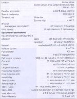
The Skyline Overland Pipe Conveyor is a single flight conveyor 2.1 miles long that drops 600 ft in elevation from the tail pulley to the head pulley. The belt travels in a west to east direction from the Skyline Mine crusher building to the existing rail loadout (Fig. 1).
The pipe conveyor includes elevated sections that allow for animal migration.
Fig 1. pipe conveyor - project specification sheet.

1.1 Unique Features of Skyline's Pipe Conveyor
-
Twenty-two horizontal curves eliminated the need for straight conveyors with intermediate transfers and the associated cost of dust control, electrical power supply and maintenance. Forty-five vertical concave and convex curves are incorporated in one pipe Conveyor
-
DC drives at head and tail control belt speed, optimizing material loading and energy consumption
-
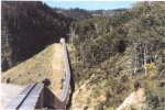
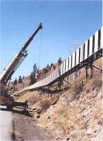
Maintenance vehicle rides on the top of the conveyor structure (Fig. 2)
Fig. 2 Typical conveyor section. Guide rail on top of conveyor serves for maintenance cart, plowing snow during winter and inspection tours once a week.
-
Minimum spillage makes the conveyor best suited for environmentally sensitive areas.
-
Long distance overland single flight pipe conveyor
-
Installed in difficult hilly terrain
-
The support structure for the pipe conveyor is considerably narrower than the equivalent conventional belt conveyor, and therefore is more cost effective
-
The pipe conveyor has replaced truck haulage with all its disadvantages and associated costs. This conveyor is now an environmentally acceptable solution, closely following the existing canyon road. It was constructed with extra care to avoid erosion and damage to vegetation.
2. System Description
2.1 HP/Torque Design Requirements
When the geometry of a pipe conveyor is the same as a straight inclined conventional belt conveyor the power consumption and belt tension are generally almost equal. If the pipe conveyor is designed with curved sections as in this installation, additional power is consumed to change the material direction within the belt.
The Skyline Mine pipe conveyor application was subjected to a careful comprehensive review of both power requirements and belt tensions.
Conveyor resistances were calculated at first and later reviewed, recalculated and adjusted. The largest two factors were the belt resistance to idler roll indentation and the curved path resistance. Together they accounted for approximately 213 of the total resistance or horsepower requirement.
The second largest group of resistances included the idler rolling resistance, the load work resistance, and the belt rigidity resistance, which accounted for a further 1\5 of total resistance.
The most critical requirement is the belt starting torque which is most demanding during the winter. Special precautions are taken to prevent the belt components from being idle during below zero temperatures due to increased system friction and coal freezing effects.
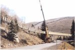
Fig 3. Setting of last truss of a total of 172 trusses. Total conveyor length of 10,356ft
2.2 Drives
A total of 1,200 HP is installed on the pipe conveyor - 800 HP at the tail and 400 HP at the head. Three Alien Bradley 400 HP, 4 - Quadrant DC drives designed for 2 minutes at 200% of load, provide variable speed and torque control for the different system requirements during starting, stopping and normal running.
All conveyor drives are 400 HP and identical. A single dove is located at the head where the take up is situated. Two drives are located at the tail end. The head drive is started first to pull the belt downhill. It is adjusted to assure proper belt tension at all times preventing slack belt from occurring at the tail drive pulley.
There are two MCC stations, both located outside of the existing buildings. Each station includes MCC rooms with associated transformer and motor controllers. The first, identified as the Drive Station, is located on an elevated platform adjacent to the crusher building.
The second, the Rail Loadout Station, is located at grade elevation, south of the head pulley.
2.3 Conveyor Trusses
Ninety-two percent of the pipe conveyor consists of trusses. The truss portion starts at the tail end of the conveyor, is 10,356 ft long and includes 172 trusses at 60-ft length, plus one that is 36 ft long (Fig. 3). They are fabricated from square tubular steel, hinged at each end, and supported on T-bents located on concrete caissons at 60-ft centers. Each T-bent includes a lateral brace anchored to the ground with a longitudinal brace spaced as required. The trusses are enclosed with siding panels and a top roof plate. An inverted T-bar runs along the top center of the trusses as a guide for the maintenance cart (Fig. 3).
2.4 Gallery Trusses
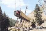
Four 165 ft long gallery trusses, plus one at 90 ft long, were supplied. Each is 10 to 15 ft in width, and are supported on gallery bents. Tubular steel bents are de- signed with two or four legs as required by the terrain. A state road runs under one of these galleries (Fig. 4).
Fig 4. Construction of head end gallery across main road.
2.5 Gravity Take-up
The gravity take-up unit is located on the return side approximately 80 ft from the head pulley. This unit is complete with two bend pulleys and a take-up pulley with carriage, as well as a counterweight box containing steel bars and punching. The counterweight box is protected from the elements by a deflection plate. The carriage and counterweight are tied together with guide channels lined with anti-friction material. The unit travels Inside two vertical steel posts tied to the underside of the gallery truss. The GTU features a removable electric chain type, 15 metric ton capacity, maintenance hoist to be used in the lifting of the counterweight.
2.6 Idler Panels
Double hole (12 rolls) and single hole (6 rolls) idler panels are installed at 6 ft or 7ft 6 inch centers.
2.7 Pipe Conveyor Belt
The belt was manufactured for Krupp Robins by the Bridgestone Tire Company and it is of steel cord construction. Specification of this belt is ST 1 000, 9 mm top and 6 mm bottom cover, 1,600 mm wide and 22,700 ft long. A layer of transverse fabric is used both above and below the steel cables. As with the fabric construction, a layer of rubber separates the fabric and the steel cords. A special carcass construction is used for the pipe conveyor. It is similar to that used for conventional belt conveyor but incorporates the following important features in its design:
The need for both stiffness and flexibility requires the belt to have sufficient stiffness to form and maintain the pipe shape as it passes through the circle forming idler rolls.
The belt edge stiffness is reduced to assure that a seal is maintained at the overlap so that material does not escape. Further, the top and bottom rubber grades and curing times are controlled to enhance the belt's natural tendency to assume the pipe shape.
Conventional conveyor belt does not have the necessary stiffness and flexibility. It would rest mainly on the bottom support idlers and consequently suffer premature cracking and fatigue. The belt life of a pipe conveyor belt and a conventional belt are virtually the same.
Belt cleaning is accomplished with the same equipment that is used on conventional belt applications, single blade and multiple blade belt scrapers and return belt "V" plows may be used.
2.8 Control
Coal from an 8,000t mine storage silo is loaded onto a belt conveyor by seven vibratory feeders at a rate ranging from 0 to 1,400 t/h. The coal is fed through a crusher and then one of three choices is possible: (a) divert to the truckload out system; (b) divert to the pipe conveyor; or (c) split between the truckload out system and the pipe conveyor. The coal diverted to the pipe conveyor is transported a distance of 2,1 miles downhill to the discharge head pulley where it is again diverted to either (a) outside stockpile storage, or (b) another belt conveyor which fills two 15,000t rail loadout silos.
The control system consists of five independent Alien Bradley PLC processors and one desktop computer which are linked together with Data Highway Plus communications. These PLOs separately control coal feeding, crushing, truckload out, the pipe conveyor and rail facilities. This allows independent operations of the truck loadout, pipe conveyor or rail loadout areas when required.
The operator stations are normally unattended. Three Alien Bradley operator interface stations are provided at strategic locations. Two Panel view 1200 keypad color terminals, and desktop computer with Control View software are provided. With the exception of belt stopping capability only one operator station is allowed to control the system at a given time. Operators can control coal feed rate from the mine storage silo and run coal to the truck loadout, rail loadout, or both. Once the system is started an ultrasonic level control system is used to control pipe conveyor speed and maintain a consistent belt fill.
2.9 Idlers and Spacing
When the pipe conveyor is straight and without any vertical or horizontal curves, the bottom three idlers of the load carrying side support the belt and material load, the top three idlers maintain the belt in its pipe shape. Should the conveyor have both vertical and horizontal curve sections, then the other idlers that surround the belt may be the load supporting idlers, while the remaining idlers maintain the belt in the pipe shape. The bottom or return belt side of the pipe conveyor have pipe shape keeping idlers only (Fig. 5).
The diameter and spacing of idler sets are determined by the size of the pipe conveyor and the material it conveys. Due to the rigidity of the belt's pipe shape, the idler spacing can be increased without excessive belt sag as with conventional conveyors.
The final selection of idler spacing is based on a complete review of the static and dynamic tension conditions of the individual pipe conveyor and the type or combination of curves that may be used.
In the area of transition at the tail end where the belt goes from the flat to pipe shape, the belt is supported by idlers with variable incline end rolls. At the beginning of the pipe shape a special idler set is used containing 12 idler rolls arranged in an offset hexagon. The resulting 12-sided figure approximates a circle closer than the standard idler hexagon and is capable of the higher loads of the closing belt. In addition to these idlers, a special single roll guide idler is used to press one edge of the belt below the other edge as the belt comes together.
The length of the transition between the tail pulley and the pipe shape, and from the pipe shape to the discharge pulley is a function of the pipe conveyor diameter and belt tension.
2.10 Thermal Expansion/Contraction
The cantilevered gallery conveyor truss is anchored to the ground at a take up tower located about 758 ft frorn the head end.
The gallery length will move horizontally a total of 6 inches due to the difference in winter/summer temperatures (-40 deg F to +100 deg F). The gallery sections expand away from the anchor point.
2.11 Chute Work
All chutes are sloped at a minimum 60' angle and valley angles are 60' or greater.
The loading chute at the tail end interfaces between the existing crusher discharge chute and the new pipe conveyor. Two chute-plug sensors are installed in the side plate of the unit. One sensor indicates material back-up for the conveyor speed control system and the second unit indicates a plugged condition for emergency action. Skirtboards include a vertical knife-gate (manual leveling device) for use with the ultra-sonic level sensor, which measures the height of material on the belt and slows down or speeds up the belt as required, for a constant filling of approx. 70% of pipe area.
The head-end chute work includes the three assemblies: a discharge chute, a transfer chute, and a purge chute.
The purge chute (approx. 10 ft long) is supported from the underside of the discharge chute, and is used when there is an emergency/upset condition. The coal is deflected from the transfer chute path (by the purge gate located in the discharge chute) and forms a pile at the grade elevation below.
2.12 Belt Transitions (Tail-End and Head-End)
The belt transition areas are equipped with snubber rolls, castor wheels, adjustable transition idlers, impact bars, and other equipment to form the flat belt into the required pipe cross-section.
3. Significant Advantages of the Pipe Conveyor
Skyline Mine engineers evaluated various conceptual designs and finalized on the pipe conveyor. The most significant advantages were:
-
the flexible design that allows the conveyor to negotiate sharper radii compared to conventional conveyors, and
-
the containment of coal within the pipe.
3.1 Mode of Operation
The material is conveyed contained within the rolled pipe shape belt. The loading of the pipe conveyor is exactly the same as the conventional conveyor belt, which is through a loading chute and skirt boards near the tail pulley. Immediately following the loading area the belt is rolled into the pipe shape with a seal formed at the top by overlapping the edges of the belt. The conveyed material is within the pipe shape belt, minimizing coal spillage.
3.2 ?????????????????????
3.3 Arrangement of Idlers
The idlers arranged to form a hexagon are used to support and guide the pipe shaped conveyor.
The idlers form a circle and constrain the belt on all sides allowing relatively tight curves to be negotiated in any direction. The curve can be horizontal, vertical or a combination of both. The elimination of transfer stations also disposes the need for additional pulleys, chutes, dust collection or dust suppression equipment, foundations and power distribution. Therefore, product degradation is also significantly reduced. Most important, the associated maintenance of a transfer point is completely removed.
3.4 Pipe Shape for Return Belt
Another meaningful pipe conveyor feature is that the return belt is also formed into the pipe shape. The belt is rolled so that the overlap is placed at the bottom of the pipe shape. This not only allows the conveyor to negotiate the same curved route as the carrying strand but it also encloses the dirty side of the belt. The possibility of dripping or scattering material that may have carried over to the dirty side of the belt is therefore minimized. This was very important to Skyline Mine.
3.5 Negotiating Steep Angles of Inclination
The pipe conveyor can negotiate much steeper angles of inclination than a conventional belt conveyor. Due to the round cross-section, increased contact area between the material and the belt occurs that allows an angle of inclination of approx. 27 deg. At Skyline Mine, the steepest inclination is 11 deg.
3.6 Volume of material carried
Another important quality is that a pipe conveyor can transport the same volume of material as the conventional belt conveyor that is typically 2.5 to 3 times the size of a given pipe diameter. As an example, a 300 mm (12 inch) diameter pipe conveyor will convey the same capacity as a 30 inch wide conventional belt conveyor using 350 troughing idlers and a 200 surcharge angle. This translates to a support structure for pipe conveyor that is only 25 inches wide in comparison to the conventional belt conveyor that will require, at a minimum, a width of 41 inches for its support structure.
3.7 Standard Components
The same standard components that are used for conventional conveyors are also used for the pipe conveyor. Since the pipe conveyor belt is flat at all head, tail and take-up pulley locations, and because the belt speeds are similar, standard conventional conveyor pulleys, bearings, and drive components can be used. The conveyor belt itself was manufactured by Bridgestone in Japan. The use of standard components available from the local marketplace makes the pipe conveyor very acceptable as it uses equipment that operators are familiar with and have full confidence in.
4. Conveyor Installation
The conveyor was installed during the last six months of 1992. Erection was done by TIC and supervised by Krupp Robins. Erection systematically started at the tail end and continued down the canyon towards the head. Trusses, bents, idler panels adjustment were the routine sequence of erection.
More than 400 concrete caissons form the foundation for the conveyor framework (Fig. 6). These pillars, about 2 ft in diameter, are poured 7 - 30 ft deep, depending on their location. To assure that no steel cuttings from the excavations remained, some caisson holes were actually vacuumed out.
Once the caissons were in place and secured, steel support was added and the conveyor module was welded in place.
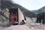
Even the short portion of the conveyor that crosses the canyon road to the storage silos was specially engineered. The roof is equipped with heated downspouts preventing cars passing beneath from being pelted with failing snow or ice.
The construction used for the diaphragm panel that supports the regreasable idlers from Continental is very simple. The panels are pressed from plate. The idler bolt-holes are jig drilled to give the required accuracy for idler mounting. Support trusses, galleries and bents are similar to those used with conventional conveyors. Due to the diaphragm affect of the idler panel, the pipe conveyor truss which does not include walkways, is much stiffer and therefore allows a lighter design. Head and tail component installation was performed at the same time. In December 1992 the construction was complete.
5. Start-Up and Commissioning
Idler alignment and proper belt loading play a key role in the stability and tracking of the pipe conveyor. On a conventional conveyor structure the idler support steel, horizontal and vertical alignment is critical for proper belt training and successful operation. With the pipe conveyor belt guided by idlers surrounding the belt on all sides, the conveyor is able to negotiate curves and centerline misalignments. During commissioning of the pipe conveyor, idler alignment to the belt is adjusted to maintain the belt overlap in a position that is located as near the top as possible on the carrying side. However, what actually assists most in belt stability and keeps the overlap at or near the upward position is the weight of the material conveyed. The center of gravity in the lower 75% cross-section maintains the proper dynamic attitude of the conveyor belt. On the return or empty side, the belt overlap is located at the bottom of the pipe shape. The extra weight of the overlap maintains the proper dynamic attitude on the return run.
Uniform feed to the pipe conveyor is important to its stability and tracking. For this reason it was recommended that feeders be used and, to assure a constant and uniform flow of material in the pipe conveyor, a monitor and variable speed drive be employed. The cross-section monitor detects the material load at the loading chute and provides a signal to vary the belt speed to facilitate a uniform cross-section at all times.
6.2 Cold Weather Operation
Special precautions must be taken to prevent the belt components from being idle during below zero temperatures due to the increased system friction and coal freezing effects.
7. Maintenance
Daily inspection of the conveyor is done by Skyline personnel in a maintenance cart which travels on the top of the conveyor trusses. The maintenance cart was installed by Skyline personnel and is an all terrain vehicle four-wheel drive unit. Additional features added were gas generators, compressor, toolbox, a snowplows for winter months.
A docking station for the maintenance cart is at the tail. The station provides a loading platform for the maintenance cart and features a 2t electric hoist. The hoist beam extends outside of the building on the south side for loading/unloading equipment. Personnel can mount/dismount the maintenance cart via an exit platform.
A daily audio inspection of the belt from the highway and a minimum weekly visual inspection from the mancart is critical to identify maintenance requirements. Preventative maintenance is of great importance in achieving the required availability of the pipe conveyor and is carried out at scheduled times.
8. Conclusion
Skyline Mine has operated the system since February 1993. A total of 22.8 million tons have been moved through March 1998.
Operating and maintenance costs have been reduced from truck haulage of 36,6 cents per ton to 4.0 cents per ton.
Environmental problems associated with coal spillage have been reduced dramatically.
Moving coal with trucks over road conditions in winter months and the costs associated with those conditions have been eliminated.
Most significantly, no coal production has been lost due to the belt since February 1993. Since January 1994, only 4 months have experienced less than 100% availability.
Acknowledgement
The photographs and operating data were provided by STAN CHRISTENSEN Of Canyon Fuel Company.
Reference
VAKA,G.A.:Pipe Conveyor-lts Development and Advantages; KRUPP ROBINS, INC.
