|
OPEN-PIT MINING
Evolution of sandwich belt high-angle conveyors
|
|
JOSEPH A. DOS SANTOS
Design Project Engineer
Dravo Corporation
EARL M. FRIZZELL
Mining Engineer
Spokane Research Center
U.S. Bureau of Mines
Abstract
Conventional belt conveyors offer an economical method for
transporting materials at inclines approaching 18 degrees. Sandwich belt
conveyors may be used to transport materials at high angles, to 90 degrees,
while maintaining the most positive features of conventional conveyors, that is,
(1) proven conventional components, (2) high speed operation, (3) high-single
lifts, (4) continuous cleaning of the smooth surfaced belts, and (5) easy, quick
repair by hot or cold vulcanizing. The present discussion deals with the
evolution and development of sandwich belt conveyors to satisfy the operational
requires of the open-pit mining and materials-handling industries.
A look at the limitations of conventional shallow and angle
conveyors reveals the conveying angle at which a cover belt is needed. The
relationship between conveying angle and hugging pressure by the cover belt is
developed mathematically. A study of past and current developments reveals that
the Loop Belt and Beltavator are significant advances in the state-of-the-art.
The vertical radius of curvature constraints are discussed in detail and
constraint equations are developed. Criteria for future development is
established as a basis for evolutionary developments in sandwich high-angle
conveyors. The use of intermediate drives in sandwich belt high-angle conveyors
is investigated.
Introduction
In connection with U.S. Bureau of Mines funded-study relating
to continuous haulage from deep open-pit mines, the authors had occasion to
study extensively, the use of high-angle conveyors as a means of hauling mine
products continuously from the pit while maintaining optimum mine slopes to
minimize total excavation. The many possible high-angle conveying methods
investigated included skip hoists, bucket ladders, pocket belts, fin belts,
cleated belts, sandwich belts, pipe belts, screw conveyors, slurry pipe lines,
and other. The sandwich belt high-angle conveyor appeared to be the most
operationally-appropriate and economical solution for the mining industry. The
present paper presents the theory, historical development, state of-the-art, and
evolutionary development in sandwich belt high-angle conveyors.
|
|
Joseph A. Dos Santos
Joseph A. Dos Santos graduated with A B.S. in civil
Enginnering in 1974 and a master of civil engineering in 1975 at Cornell
University. He subsequently took up graduate studies in mechanical
engineering at the University of Pittsburgh. Mr Dos Santos worked with
Dravo Corporation from 1975 to 1982, where he had held various
engineering positions, including proposal, design and project engineer.
His responsibilities included conceptual and final design of steel mill
and bulk materials handling equipment, feasibility studies, development
of open-pit - continuous mining and haulage systems. Since submission of
this article, the author has joined (May 1982) Continental Conveyor
& Equipment Company Inc. of Winfield, Alabama. His responsibilities
include coordination of research, development and engineering of new
innovative systems in bulk materials handling. He currently heads the
engineering, construction and demonstration of full-scale sandwich belt
high-angle conveyor (HAC) prototype. Mr Dos Santos is a Registered
Professional Engineer of New York and is an associate member of the
American Society of Civil Engineers. |
|
|
Earl M. Frizzell
Earl M. Frizzel has
been with the U.S. Bureau of Mines as mining engineer since 1975. At
present, he is developing continuous mining and haulage and reclamation
equipment and techniques for surface mining, at the Bureaus Spokane
Research Center. Prior to joining the agency, Mr Frizzell held both
engineering management positions with U.S. Steel Corporation. |
|
Keywords: Open-pit
mining, Belt-conveyors, Material handling. Sandwich belt high-angle
conveyors, Mechanically-pressed sandwich conveyor, Pneumatically-pressed
sandwich conveyor, Air-slide sandwich conveyor, S-shape conveyor, Snake
sandwich conveyor. |
|
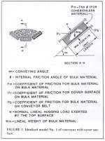
Figure 1. Idealized model
No. 1 of conveyor with cover surface |
|
|
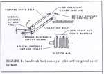
Figure 2. Sandwich belt
conveyor with self-weighted cover surface. |
|
|
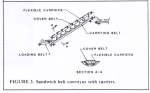
Figure 3. Sandwich belt conveyor with carriers. |
|
History and Theory of Sandwich Belt Conveyor
Limitations of Conventional Conveyors
Conventional belt conveyors offer an economical method for
transporting bulk materials at recommended inclination angles ranging from a low
of 7 degrees for soda ash briquettes, to a high of 30 degrees for cinder
concrete and ground phosphate fertilizer().
Typical recommended inclination angles for open-pit mine
products such as excavated earth and blasted, primary crushed rock vary from 15
to 22 degrees with respective angles of repose from 29 to 44 degrees(1).
The conventional conveyor is often the most economical,
reliable, and safe means if transporting bulk material(1). There are however,
many cases which strongly warrant an increase in the conveying angle. The West
Germans used high-angle sandwich belt conveyors on some bucket wheel excavators
to increase the depth of cut without increasing the boom length(2-4). A
substantial cost savings resulted from reduced structural and mechanical
components associated with the shorter boom length required to accommodate a
high-angle boom conveyor. In open-pit mines with steep mine face angles, or in
any case where the surface incline angle in the path of the conveyor
substantially exceeds that of the recommended conventional conveyor angle, much
excavation or elevated support structure is needed in order to accommodate the
conventional conveyor.
In order to logically develop the theory for high-angle
sandwich belt conveyors, it is important to understand the nature of the
conveying angle limitation for conventional conveyors.
In a static case, a cohesionless material on a rubber belt
will begin to slide back when the incline angle of the belt surface just exceeds
the angle of internal friction of the material or the friction angle at the
material to belt surface interface, whichever is smaller. The angle if internal
friction is equal to the angle of response for such materials. Both the angle of
repose and the friction angle for bulk materials on rubber will vary from one
material to the next and will be affected, even for the same type of material,
by the maximum lump size, the lump-size distribution and orientation on the
conveyor cross section, and the shape that the particles or lumps take as a
result of the reduction process, that is, blasting and the varying degrees and
methods or crushing. Although there is much published information on angles of
repose for various bulk materials(1), very little is available in the friction
angles for various bulk materials on a rubber surface. H. Colijn(5) lists
coefficients of friction of material on rubber for six different fine-grain
materials ( = tan , where is the coefficient of friction, and , is the
friction angle). They vary from 0.45 for Ottawa sand 2 pct moisture to 0.624 for
bituminous coal fines with 15 pct moisture. The respective sliding friction
angles are 24.2 and 32.0 degrees. The corresponding angles of internal friction
are not listed. An investigation by the U.S. Bureau of Mines(6) revealed much
higher friction angles when coarse material was literally displaced over rubber
belting material in a Large Direct Shear Tester. In one set of tests,
river run gravel of size 0.25 by 0.185, 0.375 by 0.25 and 0.5 by 0.375 in.
resulted in friction angles at the material to belt interface of 387.5, 42,0,
and 38.0 degrees respectively. The corresponding angles of internal friction are
43.5, 48.4, and 52 degrees. A second set of identical test of 1 by 0 in. Upper
Freeport coal, 1 by 0in. Middle Kittanning coal, by in. dolomite, and
by in. limestone yielded respective friction angles, between the material and
rubber belt, of 34.8 to 38.1, 40.6 and 33.7 degrees. The correspondence internal
friction angles are not listed.
The recommended conveying angles are, in general, far below
either of the friction angles mentioned. This is due to the dynamics induced in
a moving belt conveyor, which result in relative motion between adjacent
particles or lumps of the bulk material and between the material and carrying
surface of the conveyor belt. The three major sources of dynamic effects are:
-
The agitation of the material on the conveyor belt as it
approaches and is carried over each successive carrying idler.
This effect is
amplified when belt tension is low and idler spacing is high, thus resulting
in large belt sag between idlers.
|
|
|
|
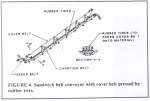
Figure 4. Sandwich belt conveyor with cover belt pressed by
rubber tires |
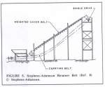
Figure 5. Stephens-Adamson Retainer Belt (Ref 8)
Stephen-Adamson |
-
The acceleration of the material at loading or transfer
points. This results in relative slip and turbulence because velocity and
direction cannot change instantaneously.
-
The vertical impact at transfer points. Such impact is
absorbed by the resilience of the belt and impact idlers and results in
bouncing of the material. This adds to the turbulence at the loading area.
These effects are increased when the belt speed is high and
even more so when the material handed is loose and contains large rounded lumps.
These effects are increased when the belt speed is high and
even more so when the material handled is loose and contains large rounded
lumps.
In 1934, A. Vierling(7) performed tests on a belt conveyor of
V-shaped or wedged-shaped cross section and showed that he could increase the
conveying angle simply by increasing the troughing angle. The conveyed materials
were brown coal, household briquettes, briquette fragments, and overburden. It
was theorized that it did not matter whether the material to be transported is
carried in a single wedge-shaped trough, using two-roll idlers, or is carried on
a belt with parallel wedge-shaped grooves, as long as the size of these grooves
is in a prescribed ratio to the size of the pieces of transported material.
His tests showed that the conveying angle could be
substantially increased only when the troughing angle exceeds 45 degrees. Tests
conducted with grooved belts conveying over-burden with a natural angle of
repose of 40 degrees showed that a conveying angle of 38 to 40 degrees could be
achieved. It is not known at what belt speed, belt tension, idler spacing, and
material size distribution these test were performed. It was announced however
that the grooved belt could convey material with mixed grain-size composition at
conveying angles 4 to 5 degrees less than the natural angle of repose.
Extrapolation of these results would lead to the conclusion
that a grooved belt is effective in suppressing the dynamic effects due to belt
travel over the idlers and in possibly creating an added normal pressure, due to
wedging action, at the material to belt surface interface. The conveying angle
cannot, however, exceed the angle of internal friction of the material at the
free surface.
Sandwich Belt Conveyors
Conveying angles greater than the angle of internal friction
can be achieved by a cover which, when pressed against the material, will create
a hugging action to prevent sliding of the control surfaces.
For a cohesionless material one can idealise the situation as
shown in Figure 1. The material is idealised as parallel layers spaced
infinitely close.
For the case where the cover surface is free to follow the
material as it slides back, sliding will occur when the tangential component of
the material weight exceeds the frictional forces which resist it or:
Wm sin α > (N + Wm
cos α)μ ....................... (1)
where:
= m or b whichever is smaller
Wm, α, N m,
b
are defined in Figure 1.
To achieve an inclination angle
α,
a normal lineal hugging load, N, must be exerted by the top surface such that:
N ≥ Wm (Sin α -
cos α) ....................... (2)
If the cover surface is fixed and it resists the motion of
the material at the interface, then material will begin to slide back when:
Wm sin α>N ( + )
+ (Wm cos α) ....................... (3)
where:
= m or
T whichever is
smaller.
T is as defined in Figure 1.
To achieve an inclination angle
α;
N ≥ Wm
(sin
α - cos α) ....................... (4)
+
If = , substitution into the above equation shows that the normal hugging load,
N, needed to prevent backsliding, is only half of that required in the previous
case (see Equation 2).
When the above principles are related to sandwich belt
conveyors, the bottom surface represents in carrying belt, while the top surface
represents any cover surface such as a pressed belt, a weighted belt, a link
chain matt, etc. For a covering surface which depends on its self-weight, the
normal hugging load N becomes the normal component of the lineal weight of the
cover surface. The second set of equations, 3 and 4, clearly show that the
required hugging load is much less if both surfaces are driven at the same
speed.
In his 1958 review of patented high-angle conveying
methods(4), P. Rasper breaks down the sandwich belt approach into three
different categories:
-
Cover belt acting by its own weight
-
Cover belt with additional pressure
-
Cover belt with carriers.
Figure 2 illustrates a category (a) solution which was
patented in West Germany in 1953. It consists of a carrying belt conveyor on
three-roll, 30-degree troughing idlers with special spring-suspended impact
idlers at the loading area, a cover surface which consists of a link chain matt,
and a cleated belt to drive the cover surface. Special grooved return pulleys
are used to carry the link cover matt.
During operation the material loads onto the bottom
horizontal portion of the carrying belt, and is carried into the sandwich where
the chain matt cover hugs the material virtue of its self-weight, and prevents
it from rolling or sliding back. The material is then elevated in the sandwich
and is discharged at the top where the two surfaces separate.
The chain matt could conform easily to the irregularities in
the material profile and this was thought to be an attractive feature. It was
noted that a cover surface which depends on its self-weight can be uneconomical
at higher conveying angles because the required lineal weight of the covering
surface increased drastically. Some elevating conveyors were built according to
these ideas.
Figure 3 illustrates a category (c) solution which was also
patented in West Germany in 1953(4). It consists of a carrying belt conveyor on
three-roll troughing idlers and a cover belt with flexible carriers of flexible
chain or rope secured to the belt at prescribed intervals along the length. It
requires a loading belt in order to place the material into the sandwich.
During operation, the material is placed into the sandwich by
the feed conveyor and it is immediately covered by the carrier. The cover belt
and carriers hug the material, by virtue of their self-weight, while it is
elevated to the discharge point at the top. The main selling feature of this
method was
claim that the cover surface was self-cleaning because of the
flexibility of the carriers. No elevation conveyors were ever built according to
this design.
|
|
|
|
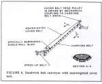
Figure 6. Sandwich belt
conveyor with nonweighted cover belt. |
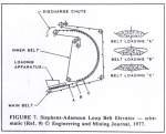
Figure 7. Stephens-Adamson
Loop Belt Elevator - Schematic (Ref. 9)
α Engineering and Mining Journal 1977 |
In his book The Bucket Wheel Excavator(2), L. Rasper
discussed the elevating conveyor illustrated in Figure 4. It is a category (b)
solution which was patented in West Germany in 1954. It consists of a carrying
belt conveyor on three-roll troughing idlers and a cover belt which is pressed
onto the material by rubber tires distributed across the belt and spaced at
large intervals along the conveyor length. A feeder belt is used to load the
conveyor.
During operation, the material is fed onto a low-angle,
uncovered portion of the carrying belt at the bottom of the elevating conveyor,
and is carried into the belt sandwich. The cover belt, which is pressed by the
rubber tires, hugs the material as it is elevated to the discharge point at the
top. According to L. Rasper(2), this solution was used in several occasions on
bucket wheel excavators of the 1950s.
As a result of his survey, P.
Rasper(4) lists three important
operational requirements of high-angle conveyors. The first pertains only to
their use in bucket wheel excavators, while the second and third are important
in any application.
-
The high-angle conveyor must provide for easy removal or
lifting of the cover belt when the conveyor is to be operated at shallow
angles.
-
The system must lend itself to easy and quick repair of
the belts.
-
Any high-angle conveyor must lend itself to easy
cleaning. Requirement 1 illustrates a recognition of additional wear on the
belt and other components when operating with the extra pressure from the
cover surface. On a bucket wheel excavator boom, such a conveyor will
operate at high-angles only when it makes the extreme high and low cuts.
During operation, a bucket wheel excavator can pick up large
boulders of different sizes and shapes, and tramp iron such as beams, plates,
etc., from previous underground mines. These can cause tears in the belt.
Requirement 2 recognises that it is impossible to guard against this so the
effort must be to minimise the consequential downtime. For a regulated and more
predictable material and size distribution, that is, the discharged material
after primary crushing, good design can reduce the frequency of damage. The
shape of the lumps cannot, however, be controlled. P. Rasper(4) suggests that
the repair can be made by hot or cold vulcanising and, on this basis, rules out
the use of fins or cleats.
Requirements 3 is based on a realisation that belts get dirty
and must be continuously cleared if they are to maintain their alignment.
Build-up of material on the belt and other surfaces also leads to additional
drag and premature wear of all support and drive components. He states that the
most popular way to clean belts on bucket wheel excavators is by screw-type
return idlers, and this requires the use of smooth surface belts. This
requirement still holds true for the many belt cleaning methods available today.
On this basis he concludes that only solution of categories
(a) and (b) lend themselves to the operation requirements and thus warrant
further study and development.
L. Rasper also points out that most of the development and
use of high-angle conveyors on bucket wheel excavators occurred in the 1950s and
that the bucket wheel excavators commissioned in the 1960s had abandoned them in
favour of higher tonnage rates and reduced belt wear of conventional conveyor(2). This reduced the cutting depth of the machine, but operational
experience showed that deep-cut cohesive soils and excavated lignite permitted
conveying angles of up to 23 and 27 degrees, respectively, with conventional
conveyors.
More recent developments in the category (a) solutions
include the Retainer Belt by Stephens-Adamson(8) and the Overlay Conveyor by
R.A. Hansen Company(11). Both claim the capability to convey material at angles
up to 45 degrees.
The Retainer Belt, as illustrated in Figure 5, consists of a
conventional carrying conveyor on three-roll troughing idlers and a heavy cover
belt with smooth rubber surface. The cover belt is shot with lead for the extra
weight needed for the normal force component.
During operation, the material loads onto the uncovered
conventional conveyor, at a nearly horizontal conveying angle, and enters the
belt sandwich prior to a gradual increase in conveying angle. The sandwiched
material is conveyed at the high angle to the discharge where the belts
separate.
The Retainer Belt conforms well to the second and third
operational requirements listed by P. Rasper(4). Other than the special cover
belt, it uses only conventional conveyor components. The higher cost of the
special cover belt, however makes the Retainer Belt expensive at high angles.
There is not apparent capacity limitation other than those which govern
conventional conveyors.
The Overlay Conveyor is illustrated in Figure 6. It also
conforms well to the second and third operational requirements set by P. Rasper,
but it does not address the need for hugging pressure to keep the material from
sliding back. It uses an ordinary (non-weighted) cover belt which is driven
along with the carrying belt by mechanical coupling. The carrying belt is
supported on three-roll troughing idlers. A specially suspended single-roll
idler presses the cover belt at the entrance to the belt sandwich. A speed-up
belt is used to feed the high-angle conveyor.
During operation, the speedup belt throws the material into
the loading area and its momentum carries it into the sandwich entrance. From
that point it is carried in the belt sandwich until it is discharged at the top
where the belts separate.
It is argued(11) that the ordinary non-weighted cover belt is
sufficient to keep the large lump from rolling back and the rest of the material
will not slide back. It is also argued that the speedup belt will throw the
material into the loading are at a prescribed speed and angle of incidence so
that the momentum of the material will carry it into the belt sandwich with a
minimum amount of turbulence. This justifies an uncovered conveyor at the high
angle.
Two test units were built to verify the theory. The first
used a 20-inch cleated carrying belt with an 18-inch smooth cover belt and a
conveyed wet sand with 10 pct rocks at 45 degrees while the second used two 60
inches smooth belts and conveyed wet sand with 10 pct rocks at a conveying angle
of 40 degrees. These test units were successful in conveying wet sand at high
conveying rates and wet sand with 10 pct rocks at reduced rates. When the rocks
exceeded 10 pct, they would roll and bounce in the loading area without entering
the sandwich. The ability to convey a limited type of material, without
additional weight on the cover belt, illustrates the advantage of driving both
belts and indicates that the effective friction angles within the sandwich may
be quite high.
In light of the state-of-the-art and current developments in
sandwich belt-type high-angle conveyors and the requirements of the present
development, two new categories (d) and (e) are added to the possible solution
types as listed by P. Rasper(4).
The current solution categories are then as follows:
-
Cover belt acting by its own weight
-
Cover belt with additional pressure
|
|
|
|
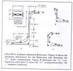
Figure 8 Stephens-Adamson Beltavator. Figure A shows the minimum
dimensions for the Beltavator and illustrates the Z shape
configuration. Figure B illustrates the L configuration and Figure C
shows the C configuration (Ref.10) Stephens-Adamson |
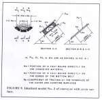
Figure 9. Idealized model No. 2 of conveyor with cover surface |
-
Cover belt with carriers
-
Belt sandwich with prying resistance by virtue of the
transverse stiffness of the two belts.
-
Belt sandwich with radial pressure by virtue of the belt
tension and the conveyor profile geometry.
The Loop Belt by Stephen-Adamson(9) represents a category
(e) solution. It is illustrated in Figure 7.
With this concept, a non-weight inner belt loop is
pressed against closely-spaced troughing idlers by an outer belt loop. The
outer belt is straight at the loading region and supported on troughing
impact idlers. When the conveyed enters the belt sandwich, the carrying
strand (outer belt loop) is no longer supported by idlers. As the belt
sandwich enters the vertical curve, the belt tension and the radius of
curvature are such that sufficient radial pressure is produced to overcome
the weight of the belt and the conveyed material. The material is thus
conveyed in a sandwich made up of the suspended carrying belt and the
idler-supported inner belt loop. This sandwich loops around, approximately
155 degrees, to the discharge point. The lineal hugging load produced by the
outer belt is determined by equation 5. As the conveying angle increases,
the vertical radius of curvature and the outer loop-belt tension must
provide sufficient radial pressure to support and hug the suspended material
in order to conveyor it up to a 90-degree angle. Above the 90-degree angle,
the material begins to sin on the supported inner belt loop; and the outer
belt loop becomes the over belt which supplies the hugging force. The
material is conveyed in this manner to the discharge point. Typically, the
outer belt loop is driven while the inner belt loop is forced to follow by
the frictional drag of the conveyed material. There has been occasion to
drive both belts by a load-sharing drive arrangements which utilises the
combined tension rating of both belts in order to maximise the elevating
height.
Pr = T/R .......................
(5)
where:
T = Outer belt tension at the point in question on the
conveyor profile.
R = Radius of curvature corresponding to the belt
tension. T.
Pr = The corresponding lineal load applied by the outer
belt.
The Loop Belt has had great success in self-uploading
ship applications and several outdoor installations. It has achieved 10,000
tones per hour, in conveying iron ore pellets and coal, and lifts up to 150
feet. Typical belt speeds are 800 to 1,200 feet per minute. A special
low-modus fabric belt is used to achieve tight vertical curves with a
troughed belt.
The Beltavator, by
Stephen-Adamson(10), is a hybrid which
represents a solution of categories (d) and (e). It is illustrated in Figure
8. The Beltavator is an extension of the Loop Belt. It is identical to the
Loop Belt up to a conveying angle of 90 degrees. At this point, it conveys
the material vertically for a desired elevating height and it again becomes
identical to the Loop Belt above the 90-degree conveying angle. It is the
straight vertical portion of the conveyor profile that qualifies as a
category (d) solution. On the straight vertical portion, the belt sandwich
is held together by closely-spaced, staggered-edge roll which press the belt
edges to keep the sandwiched material sealed between. The hugging pressure
required to convey the material at 9-degrees is provided by the prying
resistance of the two belts as the material introduced into the sandwich.
The prying resistance is by virtue of the transverse stiffness of the two
belts. The required transverse stiffness imposes a capacity limitations in
the Beltavator. As the belt width requirements become large, in order to
achieve higher tonnage rates, increasingly thicker multi-ply fabric belts
are required to provide adequate transverse stiffness. Such considerations
limit the practical belt width to a maximum of approximately 36 inches, and
maximum capacity is approximately 1 000 tons per hour when conveying dense
material. Only the outer or receiving belt is typically driven as was the
case in the Loop Belt. The Beltavator, too, has had great success within its
capacity range. It is conveying profile can follow a C Belt Path a
Z Belt Path, or an L Belt Path, as shown in Figure 8.
It is important to point out that solutions which fall
into categories (d) and (e) represent a significant advance in the
historical development of the sandwich-type high-angle conveyors. All of
categories (a) through (e) address the need for hugging pressure which
increased the frictional resistance to relative movement between adjacent
particles of the conveyed material and
between material and belt surfaces. The significance is
that solution categories (d) and (e) do not require added weight or a
pressing mechanism.
|
|
|
|
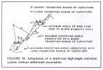
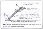
Figure 10.. Adaptation
of a multi-run high-angle conveyor system without additional excavation. |
Figure 11 Adaptation of multi-run high-angle conveyor system
with additional excavation. |
In the category (d) solution, the hugging pressure results
from prying resistance and the transverse stiffness of the two belts. This
transverse stiffness is utilised to an advantage, but it exists whether or not
it is utilised.
In the category (e) solutions, the hugging pressure results
from radial force by virtue of the tangential belt tension and the curved
geometry of the conveyor profile. Here the belt tension is used to an advantage
by the selection of a particular conveyor profile geometry. The belt tension at
any point on the profile is related to the tension at the tail pulley, the
lineal material load, and the height above the tail pulley. As with the belt
transverse stiffness, it exists whether or not it is used to an advantage by the
selection of the appropriate conveyor profile geometry.
Additional implications in category (e) solutions are
discussed when addressing the vertical radius of curvature requirements are
specified by CEMA(1).
It may seem surprising at first that Stephens-Adamson
typically chooses to drive only the carrying belt in the Retainer Belt, the Loop
Belt, and the Beltavator when it is clear from equation 2 and 4 that the
required hugging pressure is greatly reduced by exerting drag at both the
carrying and cover surfaces. A closed and more realistic look at the belt
sandwich model will reveal that both surfaces do indeed exert drag on the
material, even though only one belt is driven.
The Belt Sandwich model, illustrated in Figure 1, is very
instructive but it is not totally accurate. It assumes that the cover surface
contacts only the material, but the edges do not touch the carrying belt. It is
known that lateral movement of the cover surface during operation will cause the
edges to bear, intermittently, on the carrying belt; thus losing a portion of
the hugging load directly to the carrying belt and support idlers, while
uncovering the material at the other edge. More realistically, a minimum
distance from the belt edge to the material is required in order to assure that
the material is always covered and does not spill out. On this basis,
Stephen-Adamson chooses to derate the capacity of the sandwich type conveyors
(as compared to CEMA and capacity recommendations for conventional conveyors(1)). This assures large edge distances and, thus, a sealed envelope.
A new, more realistic model (Figure 9), illustrates the
interplay of forces. The minimum. The minimum normal hugging load, Nm; which
must be exerted on the material in order to prevent blacksliding, if both
surfaces resist motion, is expressed by equation 6.
(min) Nm = Wm (
( sin
α -
cos α) ....................... (6)
+
This follows from equation 4. The drag which must be exerted
on the material by the top surface must be counteracted by the friction drag
between the top and bottom surfaces at the edges, as expressed by equation 7.
(min) Ne e = (min) Nm ....................... (7)
The minimum required total normal load, N, can be expressed
by combining equations 6 and 7 to obtain equations 8 and 9.
(min N = (min) Ne + (min) Nm = (
+ 1)
(min) Nm ....................... (8)
е
(Min) N = (
+ 1) Wm
( sin
α - cos α) ....................... (9)
е
+
If both carrying and cover surfaces are of rubber conveyor
belting, then = .
If e = = ,
equation 9 reduces to equation 2. It will be shown later that this is, in fact,
a reasonable assumption, Equation 2 assumes that only one surface is driven. At
first impression it would seem that nothing has been gained by using the more
realistic model, because the required total normal load, N, is the same when
only one belt is driven regardless of which model is used. What is important is
the recognition of a more realistic behaviour and that only the portion of the
normal load which bears directly on the conveyed material actually contributes
to an increase in the impact on each successive idler as the material is carried
along with the belt, and thus, only this portion contributes to any increase on
belt wear. The required edge distance corresponding to the assumption that e
= = , is b/4, where be is the belt width.
What then is the advantage of driving both surfaces? If the
type of material to be handled and the environment constraints do not require a
large edge distance, then the total required additional normal load, N, can be
reduced. If there are circumstances which would cause doubt that the required
counteracting edge drag could be developed, that is e , then it would be advantageous to
drive both surfaces. In order to maximise total elevating height, it is
advantageous to drive both surfaces by a load-sharing drive arrangement so that
the combined tensile strength of both belts is utilised.
|
|
|
|
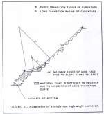
Figure 12 Adaptation of
a single-run high-angle conveyor. |
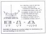
Figure 13. Stresses on a section subject to simultaneous tension
and bending in one direction. |
In light of the more current solutions in sandwich belt
conveyors a new set of operational requirements is established. This set retains
requirements 2 and 3 as originally listed by P. Rasper(4) (now numbered 4 and
5), but omits his requirement 1 because it is applicable only to high-angle
conveyors when used on bucket wheel excavators.
The combined operation requirements are:
-
The receiving end of the steep-angled conveyor must
insure that the turbulent material at the load point is settled quickly and
experience no backsliding prior to entering the sandwich.
-
The hugging pressure exerted on the conveyed material
and, thus, the additional pressure on the cover surface must be applied by a
soft loading system which minimises load concentrations.
-
The cover surface must be a floating which will not
obstruct the flow of lumps larger than anticipated or oriented unfavourably.
-
The system must lend itself to easy and quick repair of
the belts.
-
Any high-angle conveying system must lend itself to easy
cleaning.
Requirements 4 and 5, which have already been discussed,
preclude the use of carriers, and makes it impossible to cover the material
immediately as it is fed into the high-angled conveyor. The Overlay Conveyor by
R.A. Hansen Company(11) was loaded at a 40-degree angle by using a speedup to
throw the material into the loading area and allowing the momentum to carry it
into the sandwich. This was apparently successful in conveying wet sand, but
many difficulties arose when attempting to convey wet sand with 10 pct rocks. It
was found that the orientation of the speedup belt, with respect to the loading
area, was very critical and the optimum orientation varied with variations in
the mix of the bulk material. Rocks alone could not be transferred in this
manner because they would bounce and roll back But even more basically, such a
system, which depends on the momentum and angle of incidence of the fed
material, could not tolerate an emergency stop of the conveyor. It would be
impossible to re-accelerate any material remaining at the loading area after the
shutdown. Requirement 1 recognised the problems associated with loading a
sandwich belt conveyor at a high angle. On this basis, it is recommended that
the conveying angle onto which material is loaded should not exceed 10 degrees,
and the material should enter the sandwich at a maximum conveying angle of 18
degrees.
Compliance with requirement 2 will minimise the additional
wear on the belts and other components due to the additional hugging load. This
is very important because L. Rasper(2) cites the reduced belt wear of
conventional conveyors as one reason why the bucket wheel excavators of the
sixties has abandoned the use of high-angle boom conveyors.
The design must convey material which is discharged from a
primary crusher. The crusher setting only assures that in dimension will not
exceed the prescribed value. If the feed into the crusher consists of slabby
material, then a minus 8 inch setting could result in slabs of dimensions of up
to 8 by 12 by 24 inches. The loading area should be designed to assure that
slabs are oriented favourably. Requirement 3 assures that oversized or
unfavourable orientated material will not encounter pinch points and will result
only in local lifting of the cover and possible spillage of the material. It
should be emphasised that oversized lumps and slabs of the dimensions mentioned
are not to be considered part of the normal operation. If slabby material is to
be crushed, it may become necessary to reduce the crusher setting.
Constraints On Vertical Radius of Curvature
Operational requirement 1 carries with it severe
implications. After the material is loaded, the conveying angle must be
increased from 10 degrees to a much higher angle. In open-pit-mine application,
the ultimate conveying angle is dictated by the slope of the mine face. Such an
angle increase cannot be instantaneous with a troughed belt. The angle change
must be sufficiently gradual so that no part of the troughed belt is subject to
buckling or overstress. Within these constraints we must strive to increase the
conveying angle within the shortest possible distance. Figures 10, 11 and 12
illustrate why this is so.
If α represents the highest mine face angle which is
attainable because of slope stability or other considerations, then a multi-run
high-angle conveyor system may be incorporated in to the mine, as illustrated in
Figures 10 and 11.
Figure 10 illustrates the adaptation of the conveyor system
without additional excavation. The consequences of a long transition radius of
curvature are two-fold. First, the ends of each module divert farther from the
mine face, thus increasing the structural support requirements. Secondly, the
ultimate conveying and α,
corresponding to the module with long transition radius, is greater than α,
which corresponds to a module of short transition radius.
|
|
|
|
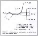
Figure 14. Idealization of multi-ply belt carried on
three-equal troughing idlers |
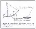
Figure 15. Transition curve of large radius does not lend itself
to a category (e) solution and the bottom left is supported on troughing
idlers. |
Thus, a higher ultimate hugging force is required to prevent
the conveyed material from backsliding.
If additional local excavation is favoured in order to reduce
the structural support requirements and to keep the conveyor profile within easy
access from the mine benches, then the conveyor system is adapted to the mine as
shown in Figure 11. A long transition radius of curvature results in increased
excavation requirements.
If a single run conveyor is used to carry the material out of
the mine, as in Figure 12, then a long transition radius of curvature requires
that the conveyor loading area extends further into the mine. In many cases it
is more efficient to locate the loading area several bench depths above pit
bottom. In such a case, the imposition is the conveyor loading area makes it
difficult to recover the material below. Depending on the slope stability
requirements, the amount of irrecoverable material can be substantial.
The equation to determine the allowable vertical radius of
curvature are listed by CEMA(1) and derived here. The final form of the
equations as derived are equivalent to the CEMA equations but are presented in a
more instructive form.
The vertical belt curve must be designed so that it will not
cause buckling nor over stress at any part of the belt cross section. CEMA, in
fact, requires that the minimum allowed tensions anywhere on the belt is 30
pounds per inch of width.
When any section of linearly elastic material is subject to
simultaneous tension, Tc, and bending, M, which is induced by the curvature 1/r
as shown in Figure 13, the stresses due to the independent forces may be
superimposed. The model assumes that the curve is smooth and that plane sections
remain plane. When applied to a conveyor belt section, this model predicts the
stresses accurately at points sufficiently far from the ends of the curve. If
the trough depth and width are much less than the length of the transition curve
and the support idlers are very closely spaced when compared to the radius of
curvature. Having made these assumptions, the bending moment can be related to
the radius of curvature by the following equation:
M = EI/r ....................... (10)
where:
E = modules of elasticity (lbs /
in.2)
I = sectional moment of inertia
(in.4)
and M and r are as defined in Figure 13.
Superposition of stresses may then be expressed as follows:
f = fa + fm = Tc
+ EI ....................... (11)
A rS
where:
F, fa, fm, Tc, A, r, S are as defined in Figure 13.
Recognising that I/S = y and substituting into equation 11
yields:
f = fa + fm = Tc
+ E y ....................... (12)
A r
Where y is the distance from the neutral axis to the extreme
outer fibers (see Fig. 13).
This equation can be applied to a multi-ply conveyor belt of
arbitrary geometry by making the following substitutions:
-
Replace the cross-sectional area A
(in.2) in equation 12 by the product of the belt width and the number of piles, (b) by (p) (in.-ply).
-
Replace the elastic modulus E (lb / in.2) by the
commercially listed belt modulus Bm (lbs / in.-ply).
Equation 13 then follows from equation 12.
f = fa + fm = Tc +
Bm y (lbs / in.-ply) ....................... (13)
bp
r
The units of stress f, fa, fm are now expressed in lbs /
in.-ply.
To prevent overstress of the bottom fibers, the combined
stresses must not exceed the working tension rating, Tr, of the belt. This means
that the following equation must be satisfied.
Tr
> Tc
+ Bm y
....................... (14)
B p b p
r
where:
Tr = Working tension rating of the entire belt (lbs)
y = distance from the neutral axis N.A. to the extreme
bottom fibers (in.)
Solving for r yields the following:
r ≥ b Bm p y
....................... (15)
Tr - Tc
To maintain a minimum tension of 30 lbs / in. on the top
fibers, the following equation must be satisfied:
30
≤ Tc
+ Bm y
....................... (16)
p
b p r
where:
y = distance from the neutral axis N.A. to the extreme top
fibers (in.)
Solving for r yields:
r ≥ b Bm p y .......................
(17)
Tc - 30 b
Next, consider a belt which is carried on three-equal-roll
idlers of troughing angle . It is assumed that the belt is divided into three
equal parts, as illustrated in Figure 14.
If the vertical curve under consideration is concave (that
is, belt edges are at inner side of curve). Then y = (b / 9) sin and y
= (2b / 9) sin . Equations 18 and 19 follow when these identities are
substituted into equations 15 and 17, respectively, and the equations are
divided by 12 so that R is the radius of curvature in feet rather than inches.
R ≥ b2
Bm p sin (to prevent overstress of
middle when curve is
concave) ....................... (18)
108 (Tr - Tc)
R ≥ b2
Bm p sin (to prevent edge buckling
when curve is concave) ....................... (19)
54
(Tc - 30b)
If a convex vertical curve is considered (that is, belt edges
are at the outer side of the curve), then y = (2b / 9) sin , and y = (b
/ 9) sin . Equations 20 and 21 follow when these identities are substituted
into equations 15 and 17, respectively, and the equations are divided by 12 so
that R is in feet rather than inches.
|
|
|
|
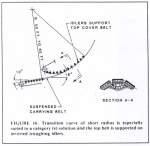
Figure 16. Transition curve of short radius is especially suited
to a category (e) solution and the top belt is supported on inverted
troughing idlers. |
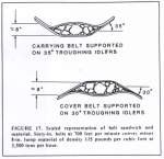
Figure 17. Scaled representation of belt sandwich and material.
Sixty-in. belts at 700 feet per minute convey minus 8-in. lump material of
density 115 pounds per cubic foot at 3,500 tons per hour. |
R ≥ b2
Bm p sin
(to prevent edge
overstress when curve is
convex) ....................... (20)
54
(Tr - Tc)
R ≥ b2
Bm p sin
(to prevent buckling
of center when curve is convex) ....................... (21)
108 (Tc - 30b)
Equations 18,19, 20 and 21 are equivalent to the CEMA
equations(1) and apply to multi-ply fabric belts. For steel cord belts,
equations 18, 20, and 21 are applicable if p = 1 and the elastic modulus Bm is
in (lbs / in.). When the curve is concave, the belt edges of a steel cord belt
are allowed to buckle to the extent that it is not detrimental to the operation.
To reflect this, the right-hand side of equation 19 is divided by 2.5, thus
yielding equation 22.
R ≥ b2
Bm p sin (allow edge buckling
in steel cord belt of concave curve) .......................
(22)
108 (Tc - 30b) 2.5
where
p = 1 and Bm is in (lbs / in.)
Equations 18 through 22 reveal the governing parameters as
they relate to the allowable radius of curvature. The belt width, b, and the
troughing angle, , must be established ahead of time so that they are
compatible with the capacity requirements and maximum lump size of the material
to be handled. For any solution of category (e), it is established that the
trough depth shall not be less than the maximum lump size (that is, for belt on
three-equal-roll idlers, then (b/3) sin > maximum lump size). With belt
width and troughing angles established, the remaining variables are the
composite elastic modulus of the belt, Bm p (lb/in.), the rated working tension,
Tr (lbs), and the operating belt tension at the point under consideration, Tc
(lbs). For a concave, curve, equations 18 and 19, applicable to multi-ply fabric
belts, or 18 and 22, applicable to steel cord belts, must be satisfied
simultaneously. Tc may be increased by an increase in tail tension in order to
counteract the buckling tendency but not to the point where the working tension
rating. Tr, is exceeding. The same arguments apply to equations 20 and 21 for
convex curves. In order to minimise the radius of curvature without violating
the governing equations we must seek a belt which maximizes the ration of the
rated tension to the elastic modulus (maximum Tr/Bm p)). However, very low
values of Tr cannot be acceptable because this would severely limit the
elevating height of any single run. The nylon-by-nylon reinforced fabric belts
seem to offer the best solution of the commercially-available multi-ply fabric
belts. In addition, it is possible to order a special nylon-by-nylon belt of
reduced elastic modulus, Bm. The cost of such a special belt is higher, but
installations in limited space many require a very short vertical radius of
curvature and, thus, warrant the extra cost. The Loop Belts installed by
Stephens-Adamson on self-unloading bulk carrier lake ships incorporate a special
low-modulus belt. An added benefit is that the tail tension on the carrying
belt, required to suspend and hug the material at the sandwich entrance of the
Loop Belt, is reduced by the reduction of the radius of curvature by equation 5.
If we consider a standard nylon-by-nylon fabric belt, 60
inches wide, carried on equal-roll troughing idlers at 30-degree troughing and
subject to a convex curve, we could expect a minimum allowed radius of curvature
in the range between 50 and 80 feet. The variation is due to the different
standard elastic moduli listed by the various manufacturers. One could expect
radii of curvature to one half of this value if a special low-modulus belt is
used. With a steel cord, belt, the minimum allowed vertical radius of curvature
would typically exceed 10 times that of the standard nylon-by-nylon fabric belt.
In open-pit mine applications, the steel cord belt is feasible only in a
single-run application with the substantial penalty of making it difficult to
recover the material below the transition curve, as illustrated in Figure 12.
When large transition curves, such as required for a troughed
steel cord belt, are used to increase the conveying angle from 10 degrees at the
loading area, to the ultimate angle of the mine face; a category (e) solution is
not possible along the transition profile (see Fig. 16) because the
corresponding belt tensions, as dictated by equation 5, are not practical. If
category (a) or (b) solutions are employed, as shown in Figure 15, then an
additional constraint applies to the transition curve. Because the carrying belt
is supported on troughing idlers and is uncovered from the 10-degree angles at
the loading area to the 18-degrees angle at the sandwich entrance, uplift of the
belt in this region must not occur when starting or running empty. Typical
operating tensions in this region will probably not cause uplift the empty belt
but, if it is necessary, the added load of the covering system may be applied at
angles lower than 18 degrees or prior to the start of the transition curve in
order to insure that uplift does not occur.
Transition profiles of short radii of curvature, such as may
be obtained with nylon-by-nylon multi-ply fabric belts, lend themselves to a
category (e) solution. This is illustrated in Figure 16. The belt tension
required at the tail
end to suspend the material and carrying belt, as dictated by
equation 5 is low enough to make this solution very attractive.
|
|
|
|
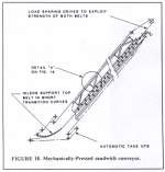
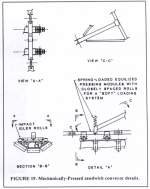
Figure 18. Mechanically-Pressed sandwich conveyor. |
Figure 19. Mechanically-Pressed sandwich conveyor details. |
Utilising 2 nylon-by-nylon fabric multi-ply belts, driven by
a load-sharing drive system, net elevating heights of up to 350 feet could be
obtained without oversizing the belts specifically to maximise lift. A
single-run conveyor, utilising two steel cord belts driven by a load-sharing
drive system, could achieve practical elevating heights of up to 900 feet. In
mines with depths exceeding 900 feet, the high-angle conveyor system could
consist of fabric
belt conveyor modules of short transition radius, arranged as
shown in Figure 10 or Figure 11; or a single-run approach, as in Figure 12,
utilising steel cord belts, or a combination of both. The single-run approach is
attractive because it eliminates the need for additional intermediate transfer
points and reduces the number of pulleys and drive components. For multi-level
operation with conveyors of varying lift required, any single-run lift exceeding
350 feet would require steel cord belts, and this a long transition profile,
causing an imposition into the mine pit which would limit material recovery.
A strong desire to achieve lifts greatly exceeding 350 feet,
without the penalty of a long transition radius, let to the investigation of a
method using a steel cord carrying belt and a fabric cover belt with
spring-mounted pivoting wing rolls at the idlers of the transition curve. The
operational characteristics of this method proved unsatisfactory and it was not
pursued further.
Evolutionary Concept for Future Development
Before introducing new concepts in sandwich belt being
high-angle conveyors, it is appropriate to establish criteria which recognise
the positive and negative features of past developments, and serve as the basis
for evolution of these into operationally superior new concepts.
Criteria for Development of Sandwich Belt Conveyors
All new developments in sandwich belt high-angle conveyors
must address the theory and constraints discussed and should judiciously select
and incorporate the desirable features of past developments while omitting,
where possible, those features which are not considered desirable.
In addition to the five operational requirements already
listed, new developments in sandwich belt high-angled conveyors should conform
to the following specific criteria. Criteria 4, 5 and 6 apply specifically to
hard-rock material discharged from a primary crusher, set at 8 inches maximum
lump size.
-
Design coefficients of friction at the belt surface to
material and belt surface to belt surface interfaces are taken as .5 which
corresponds to a friction angle of 26.6 degrees.
-
The belt width is sized so that the cross sectional area
of material, corresponding to a uniformly loaded conveyor operating at
capacity, is less than the cross-sectional area recommended by CEMA(1) for a
conventional conveyor with 0-degree surcharge angle.
-
The trough depth of the idler-supported belt in a
category (e) solution is equal to or exceeds the maximum lump size.
-
Belt speed is approximately 700 feet per minute and does
not exceed 750 feet per minute.
-
All carrying idlers are of three-equal-roll troughing
type and all idlers conform to requirements of CEMA Class E7.
-
Minimum wear cover thicknesses are:
3/8
inch carrying belt.
inch cover belt
Grade of Rubber: RMA 1 (Rubber Manufacturers Association)
The design coefficient of 0.5 between conveyed material and
rubber surface, as established in Item 1, reflects the authors1 best estimate in
light of the limited amount of data available in this area.
Because the material is totally bounded in the sandwich,
local impact as the material is carried into and over successive carrying idlers
is, to some extent, cancelled by the resisting reaction of the cover belt. The
present of the hugging force and elimination of the rolling tendency of the
larger lumps, which rise to the top surface, assure a nearly static frictional
resistance to movement at the material to belt surface interface. This value is
thought to be conservative; but because of a lack of data in this regard, it
provides a reasonable design criterion.
A design friction coefficient of 0.5 for the interface
between two belt surfaces, as established in Item 1, is consistent with the
values used in calculating frictional development in belt-on-belt-type
intermediate drives. It takes into account surface wear and the introduction of
dirt and moisture.
It is very convenient to have equal values for these friction
coefficients, because the additional pressure to transmit relative drag between
the two belts, in addition to that required to hug the material, does not depend
on the material-free edge distance. This means the prediction of an exact
configuration of the sandwich cross section during operation is not necessary.
This may be verified by considering equation 9 and reviewing the discussion
which precedes and follows it. This becomes important when considering a
load-sharing drive arrangement.
Item 2 is an artificial way of achieving the desired cross
sectional configuration for a belt sandwich at the rated capacity. A scaled
representation is shown in Figure 17. It can be seen that such a configuration
yields ample edge distance to assure a tight, leak-proof seal and a margin for
overload. It should be noted that Item 2 represents a derating of the belt cross
section by approximately 50 pct when compared to a conventional conveyor with a
surcharge angle of 25 degrees (as recommended by CEMA for conveying hard rock,
lumpy material.
Item 3 reflects the experience of Stephen- Adamson with the
operation of Loop Belts. It assures a relatively-smooth hugging pressure
distribution without excessive local stretching anywhere on the belt. As noted,
this criterion applies specifically to those methods which incorporate category
(e) solutions. It turns out that all methods which use a short transition radius
to increase the conveying angle from the loading area to the mine face angle do,
indeed employ a category (e) solution.
Item 4 sets a conveyor belt speed which will assure smooth
operation and extended life of the components. It reflects CEMA recommendations
and the experience of industry, domestic and foreign, in conveying hard lumpy
material.
Item 5 establishes that the most rugged idlers (the highest
CEMA Class) shall be used in accordance with the requirements of continuously
conveying hard and lumpy material in a harsh outdoor environment.
The RMA grade and minimum rubber cover thickness listed in
Item 6 are as recommended by belt suppliers.
The Mechanical-Pressed Sandwich Conveyor
The Mechanically-Pressed sandwich conveyor is illustrated in
Figure 18 and 19. As noted in previous discussion, conveyors which relied on a
self
weighted cover belt did not prove to be economical for
conveying angles approaching 45 degrees. The category (b) Mechanically-Pressed
conveyor, illustrated in Figure 4, had limited success on bucket wheel
excavators but was eventually abandoned, for reasons which included the
accelerated wear of the belt and other components. This is not surprising
because the total required hugging load is applied as large discrete loads
spaced at large intervals along the conveyor. Operation requirement 2 address
the problem by calling for a soft loading system which minimises load
concentrations.
|
|
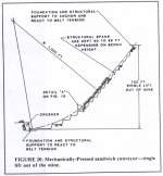
Figure 20.
Mechanically-Pressed sandwich conveyor - single lift out of the mine. |
The Mechanically-Pressed sandwich conveyor fulfils all of the
established operational requirements. It is well suited to a module approach,
utilising nylon-by-nylon fabric belts of short vertical radius of curvature, as
illustrated in Figure 18, as it is to a single-run approach utilising steel cord
belts, as illustrated in Figure 20.
Modular Approach
The modular approach combines a category (e) solution at the
transition curve with a category (b) solution on the straight run. The hugging
load on the straight-run portion is by totally equalised standard impact idler
rolls. The equalisation is to achieve a soft loading system, as established in
operational requirement 2. The pressing force is by deflection of the loading
springs and therefore increases as required with increasing conveying rate.
Design trials at 6,000 tons per hour for simultaneous
requirements of conveying at mine slope angles from 40 to 50 degrees achieved an
elevating height of 330 feet. Two 84-inch standard multi-ply nylon-by-nylon
fabric belts are supported on 20 degree troughing idlers along the transition
curve of 60 feet radius of curvature, and carried on 35 degree troughing idlers
on the straight portion. A load-sharing drive arrangement is used to maximise
elevating height.
The conveyor profile lends itself to support by a straight
truss with intermediate portals and access from any bench level. The simple
geometry and proximity to the mine face facilitates fabrication and erection.
Such a unit is self contained because belt tensions are taken through axial
compression of the main truss and no external belt anchorage is required.
Single-Run Approach
A single-run, mechanically pressed sandwich conveyor was
designed at 6,000 tons per hour for a 50 degree mine slope angle. Two 72 inch
standard steel cord belts are carried on 35 degree troughing idlers and driven
by a load-sharing drive arrangement to achieve an elevating height of 750 feet.
This is illustrated in Figure 20. This is entirely a category (b) solution. Use
of steel cord belts make it necessary to use a 1,000 foot transition radius of
curvature, and, thus, the imposition into the mine pit.
Because of the much increased conveyor length, large
foundations are required at each end to de-couple the high belt tensions from
the remaining structural support. This might actually result in a support
arrangement which is more economical in fabrication and first erection, but
mobility is not as good.
|
|
|
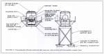
Figure 21.
Pneumatically-Pressed snadwich belt conveyor
cross section and
intermediate support bent.
|
The Pneumatically - Pressed Sandwich Conveyor
Although the mechanically pressed sandwich conveyor is a
great improvement over the solution of Figure 4, it can be seen in Figure 19
that local wear patterns on the cross section would result at the edges of the
pressing rolls. The consequences of such wear patterns, as they affect the belt
life, need further investigation. The pneumatically pressed sandwich conveyor of
Figure 21 improves on this situation by applying the hugging load onto the cover
belt by a soft air cushion.
Otherwise it is identical to the mechanically pressed
sandwich conveyor and lends itself equally well to a modular approach; which
combines a category (e) solution at the transition curve with a category (b)
solution on the straight run, as to a single run approach, which is entirely a
category (b) solution.
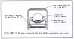
The Air-Side Sandwich Conveyor
The air-side sandwich conveyor attempts to take the
pneumatically pressed sandwich conveyor one step further by supporting the
carrying belt on an air plenum, rather than carrying idlers. A modular approach
still uses loading impact idlers and support troughing idlers at the transition
curve in a category (e) solution, but it uses a support air plenum and a hugging
air plenum on the straight portion in a category (b) solution. This is
illustrated in Figure 22. The single run approach would use impact idlers at the
loading area and a support air plenum and hugging air plenum elsewhere in a
solution which is category (b) only.
Although the air pressure system offers the softest possible
hugging load, there are many problems envisioned when it is used in a dirty
outdoor environment.
Contaminated air can clog filters and wear down the high
speed machanical parts of the pressurisation system. Failure of the
pressurisation system will result in a loss of the hugging load, and a backup
system is required. Because the air plenum which presses the cover belt is in a
fixed position, it is necessary to minimise the air gap between the plenum
skirts and the cover belt in order to keep the additional energy requirements
for the air system within reason.
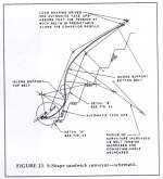
The S-Shape Sandwich Conveyor
The S-shape sandwich conveyor is illustrated in Figures 23
and 24. This concept is truly evolutionary in that if follows logically from the
Stephens-Adamson Loop Belt and Beltavator but avoids the shortcomings of each
system. It is a category (e) solution which depends on the radial force
generated by the belt tension and curvature of the profile. The constraints on
the radius of curvature, as discussed previously, dictate the use of nylon
fabric multi-ply belts.
As stated previously, the Beltavator is identical to the Loop
Belt up to and above the straight vertical run portion. It is the straight
vertical portion which limits the ability to achieve high conveying rates. Lets
consider the Z Belt Path Beltavator, as illustrated in Figure 8. If the straight
vertical conveying portion is eliminated, and the remaining curved portions are
joined, the essentials of the S-Shape sandwich conveyor remain. In addition, the
relationship between belt tension and curvature is used optimally by continually
varying the radius of curvature along the conveyor profile, as shown in Figure
23. The continual variation of the curvature is very important in achieving the
maximum lift within the geometrical constraints, that is, conforming to the
specified mine slope, and in achieving extended life of the conveyor belts and
idlers by providing only the hugging force necessary at a given point on the
profile.
The highest radial force requirement is at the bottom portion
of the conveyor where the belt tension is lowest. From the last support idler of
the receiving area to the sandwich entrance, the radial force must be sufficient
to overcome the lineal weight of the conveyed material and the carrying belt
with adequate provision for possible overload. As the conveying angle increases,
the radial component of the material load decreases, but the tangential
component increases, thus increasing the hugging pressure requirements to
prevent backsliding of material. Calculations show that the same radius of
curvature is consistent with the requirements from the loading area to the
inflection or reversal point of the profile. Because the carrying belt tension
is lowest in this area, equation 5 dictates that the radius of curvature is
also shortest in this region. Above the inflection point, the carrying belt is
supported by idlers, and the cover belt provides the radial force to hug the
material. The top belt tension at this point is chosen so that both belts will
reach their working rating simultaneously at the drive pulleys where a load
sharing drive arrangement is employed to take full advantage of the working
tension ratings of both belts. As we proceed upward along the conveyor profile,
the belt tension increases linearly with height; while the conveying angle
gradually decreases, thus decreasing the hugging requirements on the conveyed
material. This means that the radius of curvature increases rapidly, as shown in
Figure 23. Failure to increase the radius of curvature, as shown, would result
in excessive radial force which would result in accelerated wear of the belts
and would require closer spacing of idlers.
|
|
|
|
Figure 22. Cross
section of the Air-Slide sandwich conveyor. |
Figure 23. S-Shape
sandwich conveyor - schematic. |
In effect , the conveyor dictates its own geometry, and that
which is consistent with the mine slope and the desired elevating height is
determined by trial and error.
The ability to predict minimum operating belt tensions along
the conveyor profile, which is essential in designing the profile geometry, is
greatly dependent on the use of automatic take-up arrangements at the tail end
of each conveyor belt and a load-sharing drive arrangement at the head end. The
drive arrangement consists of a drive unit at each head pulley, with a control
system which causes the drives to share the conveyor load proportionally to the
relative belt stiffness, regardless of the conveying rate. The use of the
automatic take-up arrangements allows prediction of the belt tensions with good
accuracy at the tail end of the conveyor, while the load-sharing drive system
allows prediction of belt tensions at the head end with an accuracy which is
dependent on the characteristics of the load-sharing drive arrangement. A 10
percent tolerance in the relative belt tensions at the head end is considered
acceptable and incorporated into the design of the components. With the belt
tensions known at the head and tail ends of the conveyor, it must be assured
that the increase in tension between the two ends, which is due to material
load, self-weight of the belts, frictional drag, and acceleration /
deceleration, is distributed to the two belts in proportion to their relative
stiffness. To assure this, no relative movement must occur between the belt
surfaces. The minimum hugging pressure must, therefore, develop sufficient drag
between the top surface and the material and bottom belt edge surface so that
slip will not occur due to the tension variation of the top belt, with respect
to a stationary material and bottom belt surface. The minimum hugging pressure
must also assure that the portion which is transmitted directly through the
material is sufficient to prevent backsliding of the conveyed material. In the
design, the ratio of the top belt stiffness to the combined belt stiffness is
chosen to approximate the ratio of the top surface drag on the material, as can
be developed by the latter minimum hugging pressure, and the total drag exerted
on the material. Adherence to the design criteria,1, 2 and 5 assures that the
former minimum hugging load requirement is fulfilled when designing specifically
for the latter.
A very sensitive area in the design of the S-Shape conveyor
is where the curvature reverses instantaneously. This is shown on detail B of
Figure 24.
Theoretically, no hugging pressure is lost if the curvature
reversal is, in fact, instantaneous. Practically, however, an instantaneous
curvature reversal is not possible, as is shown in Figure 24. A straight profile
must exist between the idlers to either side of the reversal point when the belt
cross section is fully loaded. The length of this straight portion is increased
when the conveyor is only partially loaded. Theoretically, no hugging pressure,
due to belt tension, exists on a straight conveyor profile (see equation 5). If
the adjacent idlers to either side of the reversal point are sufficiently close,
secondary resistance to prying the belts apart is instantaneous and increases in
response to the increase in spreading distance between the two belts. Such
response might make it possible to convey the material through this region
without backsliding and to hold the stationary material when a shutdown occurs
with a loaded belt. The interplay of forces is extremely complicated, and
accurate assessment requires a sophisticated analytical model.
Several preliminary design trials were performed for a
conveying rate of 6,000 tons per hour and simultaneous adaptability to mine
slope angles from 40 to 50 degrees. Utilising 84 inch wide standard multi-ply,
nylon-by-nylon fabric belts, supported by 20 degree troughing idlers, resulted
in a radius of vertical curvature at the bottom portion of the conveyor profile
of 60 feet and a maximum elevating height of 248 feet. The elevating height was
limited by the geometry of the profile when adapted to a 50 degree mine slope
angle and not by the belt tension. The high hugging pressure requirement on the
top belt in the area of the inflection point dictates a short radius of
curvature. The combined radial force exerted on the curve by the two belts
requires extremely close spacing of the support idlers to either side of the
inflection point. Moving the inflection point further upward on the profile is
not possible because the required idler spacing for an 84 inch belt would not be
physically possible with standard idlers. Higher elevating heights could be
achieved if the mine slope is decreased and / or the capacity and belt width are
decreased. The latter is because the idler load rating for a CEMA E7 is the same
for the different belt widths.
This conveyor has better geometric conformance to the mine
slope than does the Loop Belt, but it still deviates appreciably from the mine
face. Such deviation means that the structural support must consist of a long
span truss to follow the conveyor profile and react on the mine face only at the
two end points. Access from the face to the conveyor would exist only at these
end points. Such a unit would be self-contained in that the belt tensions and
loads would be taken through the truss and would not require external anchorage.
A truss to fulfil these requirements would be very heavy. Fabrication and
erection would also be more difficult than for a truss which is essentially
straight between the two end points and follows the mine face closely.
The Snake Sandwich Conveyor
The snake sandwich conveyor is illustrated in Figure 25. If
the S-Shape conveyor is a product of evolution, then the snake sandwich conveyor
is the next step in the evolutionary process. It too is a category (e) solution
and requires the use of nylon fabric multi-ply belts.
Like the S-Shape conveyor, the snake sandwich conveyor
requires the ability to predict the minimum operating belt tensions along the
profile in order to determine the profile geometry. It is thus, greatly
dependent on the use of automatic take-up arrangements at the tail end and a
load sharing drive arrangement at the head end, as previously described.
The major difference is the introduction of many inflection
or curvature reversal points on the conveyor profile, which allow for a geometry
which is much better suited to the mine face geometry. The profile inflection
points are also at lower conveying angles and, therefore, require less hugging
pressure in this region.
The radius of curvature is again, shortest at the bottom
where the belt tension is lowest and increases with height corresponding to the
increasing belt tension. The radius of curvature is continuously changing in
order to provide only the required hugging load and, thus, prolong the life of
the belt and reduce the idler requirements. Like the S-Shape conveyor, the snake
sandwich conveyor essentially dictates its own geometry and, thus, requires a
trial-and-error approach; but there is more freedom in determining the geometry
as the inflection points are introduced when convenient.
Many preliminary design trials were performed for a conveying
rate of 6,000 tons per hour and simultaneous adaptability to mine slope angles
from 40 to 50 degrees. As with the S-Shape conveyor, two 84 inch standard
multi-ply nylon-by-nylon fabric belts were carried on 20 degree troughing
idlers. The resulting radius of vertical curvature at the bottom portion of the
conveyor profile was 60 feet as in the S-Shape, but and elevating height of 330
feet, for the 50 degree mine slope was achieved with standard catalogue belts.
The elevating height was limited by the working tension rating of
the two belts, with due regard to possible intermittent overload as a result of
the inherent tolerance in the control system of the load sharing drive
arrangement. The most significant result is that a reasonable profile geometry
could be enveloped within a straight box truss of 15 foot depth. Such a truss
depth is consistent with economical truss design for such an application (when
considering the trade-offs between the additional cost of the intermediate
support portals and foundations versus the cost saving in the truss itself) and
would result in a three-point support for the design requirements stated. The
simple geometry, reduced weight of the truss and its proximity to the mine face
facilitate fabrication and erection and allow for easy access, as desired, from
any mine bench level spanned by the structure. A conveyor unit of the specified
lift and slope would be self-contained, as was described in the S-Shape
conveyor.
|
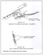
|
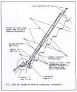
|
|
Figure 24. S-Shape
conveyor details. |
Figure 25. Snake
sandwich conveyor - schematic |
Intermediate Drives
Two types of intermediate drives were investigated for
possible incorporation into the sandwich conveyor designs discussed. The first
utilises a driving belt which pulls the carrying belts over a required
development length, as illustrated in Figure 26.
The second consists of pairs of driven tires which squeeze
the belt at the edges, and transmit a tractive force to the belt, as illustrated
in Figure 27. Both types of intermediate drives act to relieve the tension of
the carrying belt forward of the drive so that the elevating height or length of
a conveyor need not be limited, even for belts of relatively low strength. The
snake sandwich conveyor, as just described, presented an opportunity to apply
either system in an attempt to achieve a single-run conveyor. The snake sandwich
conveyor appears to lend itself especially well to the drive belt-type intermediate drive, as shown in Figure 28, and presents a
good opportunity to demonstrate the characteristics of both systems.
|
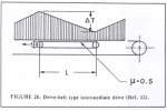
|
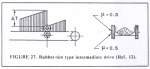
|
|
Figure 26 Drive-belt
type intermediate drive (Ref. 12) |
Figure 27. Rubber-tire
type intermediate drive (Ref.12). |
The drive belt-type intermediate drive depends on the normal
lineal force exerted by the carrying belt on the drive belt. Based on a
coefficient of friction of .5(12), the frictional development length can be
determined. The snake sandwich conveyor lends itself especially well to this
type of intermediate drive, because, there is always a substantial radial
pressure exerted by the belt sandwich along the curve, even when the material
load is absent. Also, the geometry is convenient, because, it allows the drive
belt to depart on a tangent at the inflection points of the conveyor profile
without interfering with the carrying idlers. Driving the top belt in this
manner did not prove efficient as the introduction of the conveyed material load
caused substantial relief of the radial pressure along the curve, thus reducing
the amount of frictional development.
Preliminary design for a 50 degree mine slope angle required
a contact length between the carrying belt and drive belt in excess of 50
percent of the conveyor length. This requires a drive belt at every curve which
supports the bottom belt. Many problems are inherent in a system of this type
and they are listed below:
-
Intermediate drives would be spaced at height intervals of
approximately 50 feet. A 300 foot lift would require six drive units. The
probability of breakdown is increased with the number of drives.
-
Failure to drive the top belt requires a small increase in
total hugging pressure when compared to the original design of the snake
sandwich conveyor in which both belts were driven. The increase is small
because substantial edge distance exists and frictional drag along the edges
acts to carry the middle portion of the belt.
-
The introduction of the tensioned drive belt adds to the
radial load to be supported on the carrying idlers and, therefore, requires
more closely spaced idlers.
|
Figure 28 Snake sandwich
conveyor with drive-belt type intermediate drives. |
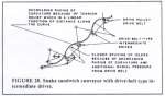
|
|
Figure 29 Snake sandwich
conveyor with rubber-tire type intermediate drives.
|
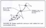
|
|
Figure 30 Straight-Run
sandwich conveyor with drive-belt type intermediate drives. |
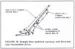
|
-
The radius of curvature must decrease along the driven
curve. As the tension on the carrying belt is relieved by the drive belt, the
radius of curvature must decrease if the prescribed radial load is to be
maintained. The hugging pressure from the op belt increases inversely to the
requirement, because its tension is constant ant the conveying angle
decreases. The radial pressure from the drive belt increases exponentially.
-
Determination of the curved profile between the driven
curves is largely dependent on the ability to predict the tension of the
carrying belt at any point on the profile when, it alone, is driven. This
means that a control system is necessary to assure that all drives contribute
equally or nearly equally to the total driving effort. The complexity of a
control system to co-ordinate load sharing would increase with the number of
drives.
Such considerations are overwhelming and the incorporation of
such drive units is ruled out.
The rubber-tire intermediate drive utilises a squeezing
pressure which allows the development of traction on the belt. Effective
coefficients of friction between the tire and belt surface were found to be from
.44 to .55 for wet and dirty surfaces(12). The combined
traction-to-squeezing-force ratio of .8, as indicated in Figure 27, is
conservative. The inflection points on the snake sandwich conveyor are logical
locations for this type of drive, as shown in Figure 29.
B.F. Goodrich and Continental Conveyor Company(13, 14) have
developed and used rubber-tire intermediate drives. Drive modules of up to 200
hp are in existence. The system utilises a special belt which has extra wear
cover at the edges and limits reinforcements, for steel cord belts, to these
edges. Testing with such drives leads the Russians(12), to the conclusion that
ordinary belts can be driven in this manner without prematurely wearing out the
cover at the edges.
Incorporating 200 hp drive modules into the snake sandwich
conveyor design, as shown in Figure 29, would require such units at height
intervals of approximately 30 feet for a conveying rate of 6,000 tons per hour,
and approximately 50 feet for a conveying rate of 3,500 tons per hour. A bigger
unit would be needed for the higher conveying rate.
Considerations 1 and 5, listed for the drive-belt type
intermediate drives, are equally applicable to the rubber-tire-type intermediate
drive. This makes their incorporation impractical.
If a straight-run conveyor is used, as few as two
intermediate drives, utilising steel cord belts could achieve elevating heights
in excess of 900 feet. This is illustrated in Figure 30. However, the penalty is
substantial because the required contact length between the carrying and drive
belts is approximately 100 percent of the conveyor length (because
= .5 for material on belt as well as belt-on-belt), and additional hugging
pressure must be applied specifically to reduce this contact length. In
addition, extra costs are incurred for drive belts, pulleys, and take-up
arrangements. Applying the rubber-tire-type intermediate drives in a straight
conveyor is no different from its application on the snake sandwich conveyor.
For the reasons discussed, intermediate drives are not
considered practical at the present stage of development.
Summary
Conventional belt conveyors offer an economical method for
transporting bulk materials at inclines approaching 18 degrees. Many
applications warrant conveying at steeper angles to 90 degrees, to minimise the
support structure and / or excavation. Of the many high-angle conveying concepts
known, the sandwich belt conveyor appears to be the best solution for conveying
at high rates, above 1,000 tonnes per hour, and achieving high lifts up to 350
feet per module. By studying the operational characteristics of past and present
sandwich belt conveyors, the authors have established the design constraints and
developed criteria for future development.
On this basis, new evolutionary methods in sandwich belt
high-angle conveying are suggested fur future development. One class of solution
is based on added mechanical or pneumatic pressure to the cover belt to develop
the necessary friction between the material and the belt surfaces. The second
class is based on hugging pressure derived by snaking the conveyor profile to
exploit the inherent belt tension in any elevating conveyor. The use of
intermediate drives in sandwich belt conveyors was investigated, but the many
complications make such drives impractical with todays technology.
References
-
Conveyor Equipment Manufacturers Association (CEMA).
Conveyors
for Bulk Materials. CBI Publishing Co., Inc. Boston, 2nd edition 1979.
-
RASPER, E.L., The Bucket Wheel Excavator, Development,
Design Application. Series on Bulk Materials Handling. Vol. 1. 1975, No.
2, Trans Tech Publications, Calusthal, Germany, 1st edition 1975.
-
GAERTNER, E., Entwieklungstenzen in der Geraete-und
Foerdertechnik der rheinischen Braunk Braunkohlentagebaue (Development
Trends of Machines and Material Handling Techniques in the Rheinbraum
Open-Pit Mines). Braunkohle, Waeme Und Energie HEFT 11/12, 1955, pp.
22-241
-
RASPER P., Bank/Steilooerden in deutschen
Braunkohlentugebau (Elevating Belt Conveyors for Lignite Open Mining in
Germany). Deutsche Hebe-und Foerdertechnik in Diente der
Transportration-isierung, Dec. 1958, pp. 22-29
-
COLIJN, H., Design Considerations for Belt-Conveyor
Systems.
Iron and Stell Engineer, August 1962.
-
WANCHECK, G.A., and FOWKES, R.S., Materials Handling
Research: Shera Properties of Several Granular Materials.
BuMines R1
7731, 1973.
-
VIERLING, A.,Die Keilband-Forderanlage, ein neues
Mittel zum Steilen Foerden Foerdern von Massenguetern.
Braunkhole Heft
11. March 1935, pp. 161-169.
-
Stephens-Adamson. The Stephen-Adamson Loop Belt Elevator.
Belleville, Ontario, Advertisement.
-
Loop belt to be installed in Port Cartier.
Engineering
and Mining Journal, February 1977, P. 114.
-
Stephens-Adamson, Beltavator, Belleville, Ontario,
Advertisement.
-
R.A. Hansen, Co., Inc. Development of Cross Pit
Overburden and Waste Material Handling System.
BuMines Contract No.
H0252084, 1979.
-
SHARIKOW, V., KRAWEZ, N., and FRITSCH, F.,
Foerderbandantriebe durch Luftreifen (Belt Conveyors Drives with Pneumatic
Tires).
Foerden und Heben, v. 11 November 1979.
-
ARGALL, G.O., Belt Conveying Not Pumping, Used by
Brewster P205 For Florida Matrix.
World Mining, January 1978, pp. 48-51.
-
Coal Age, Continuous Haulage Methods Designed to Keep
Continuous Mining Continuous, July 1976, pp. 119-136. (For Coal Age
Reprint Dept., P.O. 690, Highstown, NJ 08520).