|
Figure A-B |
Figure A and B |
| Improved High Capacity Conveyor Designs |
|
By:
Lawrence K. Nordell, President
Conveyor Dynamics, Inc.INTRODUCTION
This paper is a presentation of recent advancements in design and manufacturing techniques that lead to cost effective and safer belt conveyor systems. The featured points addressed here are:
Improved Power Analysis
Improved Belt Strength Safety Factor
Dynamic Analysis Benefits
Improved Starting & Stopping Controls
Horizontal Curve Usage
I have included a number of overland and high capacity conveyors in Tables 1 and 2. These systems represent some of the design projects at Conveyor Dynamics, Inc. where improved design concepts are used as illustrated in this paper.
POWER ANALYSIS
The traditional methods of calculating frictional losses in high capacity and overland belt conveyors is being challenged by improved procedures. The industrial standards, as setforth by CEMA, DIN, ISO, and belt manufacturers' handbooks, can yield inaccurate results. These conventional methods do not include the separate rolling resistant influences for:
idler diameter
belt cover thickness
belt cover rubber properties
belt speed which affects rubber hysteresis idler trough shape
material load patterns and pressure distribution
The standards have been simplified to allow hand held calculator analysis. The modern methods, which provide rolling resistance calculations accurate to within 10% of field measurements, include all of the above improvements, as well as other, more subtle, quantifiable influences, such as idler alignment. Modern PC grade computers can resolve these influences in a timely manner without difficulty. At Conveyor Dynamics, Inc. (CDI), we use the Hannover University (West Germany) work of W. Behrends and F. Schwarz, the work of Professor C. Spaan at the Delft Institute, and the work of C. Jonkers at Twente University (both in The Netherlands). Jonkers' methods are now employed to assess the interaction of rubber compounding and rubber-idler indention losses. From our work in coal, copper, and iron ore, using the CEMA and DIN methods, errors as large as 25% have been measured.
CEMA and DIN provide no guidelines on idler diameter influence. Research work shows, and field measurement confirms, that the idler roll diameter influence on power is significant. The roll-rubber indention loss contributes approximately 40-60% to the rolling losses. The idler diameter can influence the indention loss approximately in proportion to the idler diameter ratio:
f(rolling resistance) = (0.50)f(indention) (diameter A / diameter B), where idler diameters A and B are two sizes under study.
Increasing the idler diameter from 152 mm (6 in.) to 178 mm (7 in.) diameter on a 1050 mm iron ore belt carrying 2200 T/H reduced the calculated power 8%.
Another significant omission in the industrial standards are belt cover and carcass construction influences. A 1 mm change in cover thickness can alter the conveyor's power by 4% or more, with less than a 3% change in the belt's weight and about a 1.5% change in overall idler loading.
The belt cover rubber's visco-elastic rubber rheology is now known to have a dramatic influence on rolling loss and its power. Alteration to the cover rubber chemistry, improving its liveliness or reducing its inert properties, reduces power consumption. I believe future belt specifications will require measures of the belt properties to quantify power consumption. Research is presently conducted by leading belt manufacturers to take advantage of this recent assessment similar to the work in tire research.
Large idler spacing (greater than 2.0 m) is not referenced in the industrial guidelines. Three meter spacing and larger is now common in coal. Selby in the U.K. uses a 6.0 m carryside idler pitch over a a large portion of its 12 Km length. Only the modern methods of idler-rubber indention loss can analyze whether such spacing is an acceptable or economically advantageous concept. From our studies of long overlands, in light weight material suchas coal systems, under 2000 T/H, a 3.0 m (10 ft.) carryside pitch is close to the optimum selection. In heavier materials, such as iron ore, the ideal carry side pitch is closer to 1.75 m. In both cases we recommend the use of 178 mm diameter rollers.
Idler alignment and supporting structure rigidity impact operating power as well. The idler's rolling axis should be normal to the belt line to within 0.15 degrees (2 mm offset across the roll face of a 1000 mm belt). The power performance can be improved by 2-4% by utilizing improved accurate idler / frame manufacturing and installation techniques.
I recently assisted in the empty belt commissioning of a single flute, horizontally curved, 10 Km overland conveyor, where no idler adjustment or pulley alignment was required, due to accurate manufacturing and installation techniques. All idlers were aligned to within 1-2 mm offset normal to the belt's axis.
BELT STRENGTH & SAFETY FACTOR
Greater emphasis is being placed on belt manufacturers to improve their splice strength techniques to allow lower belt safety factors. This paper only references minimum allowable steel cord belt safety factors. Steel cord belt safety factor can be reduced below the conventional 6.7: 1 to the range of 4.5-5.0:1. The economic benefit is very substantial. Lowering the belt minimum allowable safety factor to 5.0: 1 on a 20 Km overland in Australia reduced the capital and adjusted NPV belt operating cost by approximately 10% for the 20 year mine life. The belt weight was reduced approximately 227 tomes (14%). The power consumption, of a loaded belt, dropped over 4%. Fewer splices were required. Idler life was increased approximately 7% on the carry strand and 40% on the return strand. Reduced belt tensions resulted in lower pulley and structural requirements.
The 6.7: 1 belt safety factor standard for steel cord belt is over 20 years old. Within the last six years, a number of operators have specified a belt safety factor SF = 5.0 or lower for some installations such as:
| Rhinebraun Hambach Mine (West Germany) | 4.5 : 1 | Coal |
| Selby Mine (U.K.) | 5.0 : 1 | Coal |
| Mea Mine (New Caledonia) | 5.5 : 1 | Nickel |
| Prosper Haniel Mine (West Germany) | 5.5 : 1 | Coal |
| Channar Mine (Australia) | 5.0 : 1 | Iron Ore |
The definition of belt safety factor (SF) is given to be the rated cable breaking strength divided by the steady-state full operating load, or design load. This safety factor definition is very misleading since it has nothing to do with the real design safety factor of the belt. The belt steady-state and momentary peak operating loads are dependent on splice strength, not ultimate cable tensile strength. The splice strength for the conventionally rated belt (SF = 6.7:1) is given to be about 36%, based on its dynamic fatigue tensile capacity as defined by the DIN standard 22101. Any increase in the splice dynamic load capacity (fatigue strength or efficiency) directly relates to a reduction in the apparent "industrial given" minimum allowable belt safety factor (i.e.; an increase in splice efficiency from 36% to 50% would mean a possible reduction in the SF = 6.7: 1 down to 4.8: 1 [6.7 x 0.36 / 0.50].
Improved belt safety factors have been realized through improved core rubber properties, cable construction techniques, splice engineering, and manufacturing methods. It is now possible, through finite element analysis (FEA) to predict the splice stress field in the rubber and steel cables. The FEA method of splice design allows evaluation of the many styles and splice patterns that have lead to improved splice dynamic capacity and reduced belt safety factoring. An example of this process was the development of the Palabora belt in RSA by Continental Guxnxni (FRG). Prior to Palabora, the reputed strongest rated belt was Prosper Haniel's (W. Germany) ST-7500 N/mm. The Prosper Haniel incline belt was tested at Hannover University for its splice fatigue strength capacity. It achieved 38% efficiency as measured by the fatigue machine. Thus, the splice fatigue strength is 2850 N/mm (endurance rating = .38 x 7500 N/mm). In 1987, after the design of Prosper Haniel, Palabora specified a belt at ST-6600. This belt was tested at Hannover to an endurance level of 50% with a four stage splice. The net endurance level is ST-3300 N/mm, or 16% stronger than Prosper Haniel, although its breaking strength is 14% lower. Palabora was designed with an SF = 6.5:1. From the high splice strength results, the safety factor could have been reduced to 4.7:1. Conversely, the belt is able to handle a 39% increase in tensile forces.
More recently, in 1988, CDI, on a project in Australia, assisted in the design of a ST-3000 N/mm strength belt. The belt splice was tested to a 58% dynamic efficiency at Hannover. The belt is rated at SF= 5.0:1.
I recommend that any overland belt, or high capacity belt, with SF less than 5.5:1, which has an unproven splice design, cable construction, and/or manufacturer without operating references, that the splice be tested at Hannover or an equivalent testing lab system.
A different design criterion is required at SF < 5.5:1. Since the cable stresses and splice stresses are increased, special consideration must be given to the following:
pulley diameter selection dependent on cord pressure
take-up length
manufacturer's tolerance on cable position in the belt
splice design and field installation tolerances and techniques
idler transition design at high tension zone
vertical and horizontal curve cable stresses
starting and stopping dynamic load peaks
I hope that the industrial criteria for belt safety factoring are revised to reflect the meaning of safety with accountability for the belt's true operating limits. The present design limits are given in the chart following Table 2.
DYNAMIC ANALYSIS TECHNIQUES & BENEFITS
Dynamic analysis is defined as a mathematical modelling procedure which simulates starting and stopping behavior as the belt undergoes elastic change along its length, at differing speeds at one point in time. Because of the model's complexity, and need for high speed computer power, only six commercial models have been developed and applied. Of these, five have been published, four outside communist block countries.
In 1967, Robins Engineers (Hewitt Robins, U.S.A., now a division of 0 & K), developed the first modern, commercially used, dynamic model. They have not published the model's development or results derived from it.
Conveyor Dynamics, Inc. finished development and commercially applied the dynamic model BELTFLEX in early 1980. The model's structure and initial findings were first published in 1984.
Well designed dynamic models can predict the dynamic behavior of the belt to a far greater accuracy than conventional, rigid-body techniques, and identify dangerous conditions that conventional methods cannot address. I believe most large mine operators will, in the near future, require dynamic modelling as a natural design function, when:
large expenditures are involved;
it can be shown that conventional methods are not safe at reduced belt safety factors, and accurate assessment of structural loads is specified;
manufacturers of belting and pulley assemblies want accurate prediction of loads, and when warranties are related to peak and nominal load capacities;
system reliability is paramount;
"What If' malfunctions, such as loss of certain control functions on downhill conveyors, or aborted starts of high capacity inclines are considered;
the designer is not experienced with complex interactive starting and stopping controls;
legal protection against malfeasance from system failures.
Dynamic analysis provides insight on the cause and effect relationship of starting and stopping control logic and their interaction. I believe most modern dynamicists are more knowledgeable on control functions and logic, that start and stop conveyors than are the manufacturers of the related hardware, and are therefore more qualified to recommend control concepts.
Virtually all starting and stopping methods can be modeled, including:
Across the line A.C. induction motors
Fixed and delayed fill fluid couplings
Scoop controlled fluid couplings
Eddy current brakes and clutches
Mechanical clutches (hydraulic and friction types)
Wound rotor resistor step (fixed time; speed dependent; power dependent)
D.C.-SCR drives
Hydraulic servo and stage braking
Pneumatic servo and stage braking
Holdbacks; cam engaging and mechanical brakes
A recent product of dynamic analysis is "drive mass tuning". During stopping of high capacity, and high powered conveyors, large transient stress waves are developed that can impart damaging forces into the belt, holdbacks, pulley assemblies, and take-up systems. Large transients can also produce large belt sag regions followed by excessive take-up motion where the take-up hits the travel stop.
Examples of these concerns are:
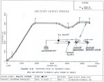
A. HOLDBACK OVERLOAD: Phelps Dodge (Morenci) requested a dynamic analysis of a high lift, 5000 HP conveyor which they were about to commission. The conveyor specifications are:
Capacity 7500 STPH Length 1.7 Km (5500 ft.) Lift 125m(412 ft.) Power 3800 KW (5000 HP) Speed 4.7 m/s (930 FPM) Belt Strength 3750 PIW Width 1524 mm (60 in.) The analysis predicted excessive low belt tensions would occur and be prominent about the tail station, followed by extreme overloading of the low speed holdbacks at the head and drive during a motor shutdown.
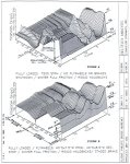
The result is illustrated in the three-dimensional (3-D) plot in Figure A. The 3-D plot shows the total collapse of drive tension in the first two seconds after the motor shutdown. During this two seconds, the head and drive pulleys dropped in speed about 30%, with a tapering of speed back to the tail. The return strand had not yet begun to slow down. The large belt compression stress pushed belt into the tail load station causing belt to accumulate between the idlers as it pulled belt out of the take-up. Ten seconds after shutdown, the holdback begins to engage and the load rises steadily to thirteen seconds, overloading the primary drive holdback. The return strand begins to run in reverse as the take-up pulls belt sag out of the tail station. At 17 seconds, a large jerk occurs as all belt sag is removed and return strand reverse belt velocity is stopped by the carry strand. The jerk produces a doubling of the tail pulley load. The jerk action propagates a tensile stress wave along both the carry and return strands. The tensile wave hits the take-up assembly in 17.5 seconds, with a doubling of the take-up force. At 19 seconds, the tensile wave hits the drive and head stations with an impact to the primary drive holdback that is about seven times the secondary holdback torque.
|
Figure A-B |
Figure A and B |
The solution was to apply flywheel mass tuning of the drive and assist with take-up motion control by applying a brake on a bend pulley between the take-up pulley and the tail. The results of the recommended improvement are shown in Figure B. The holdbacks load share with no dynamic anomalies and no belt sag problems.
The client required immediate production from the conveyor, and asked at what tonnage it would be safe to operate, before a fix could be installed. I recommended that until the tuning system was installed, 1/3 of the design capacity was acceptable. At 1/3 tonnage, there would still be pronounced belt sag and dynamic whip of the belt at the tail. The belt was loaded to 1/3 tonnage and tested. The prediction was accurate. The client then continued to test at higher tonnages up to 5000 TPH. At 5000 TPH, a shutdown was initiated that resulted in ore being catapulted about the landscape when the return strand jerk hit. The tonnage was then reduced to 1/3, until the fix was installed.
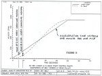
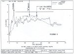
B: TAIL PULLEY OVERSTRESS: This example is from a study done for British Coal Company on their Selby drift conveyor. This is illustrated in Figure C. This sketch shows the measured versus calculated tensile stress wave propagation along the belt's 12.2 Km length (head to tail) caused by the collapse of driving power. The loss of 80 tonnes of driving power creates a 40-46 ton tensile and 40-46 ton compression wave that travels down the return and carry strands simultaneously (one ton = 2204 lbs.). The 40 ton (measured) tensile wave travels down the return strand hitting the tail station at virtually full force 5.5 seconds after shutdown. The sharp tensile impulse is followed by an immediate collapse of this force, starting 1.0 seconds later, caused by the drive compression wave that travelled down the carry strand. The design engineer was asked by the client why they had not designed for this condition. The engineer stated that they thought the wave energy would collapse in friction and rubber hysteresis from the 12 Km path before hitting the tail station. Note, at full tonnage and speed, the tail station is subjected to a force over four times the running load. A similar design evaluation was made of the Chuquicamata 8000 HP incline belt. It showed an identical pattern where the tail tension shock load was about 12 times the running load.

Figure C
The load cell measured data was taken from a test at a lower tonnage and tensile force than the calculated peak design load. When the two values are adjusted for the same data, the results are very similar (less than 5% difference in wave intensity).
STARTING & STOPPING CONTROLS
Conventional starting and stopping ramp controls utilize a "linear" acceleration and deceleration velocity vs. time ramp. I recommend the use of an "S"-band acceleration curve over the linear for the following reasons:
reduction in belt peak stress by up to 15%
reduction in peak motor torque demand
reduction in potential drive pulley slip on belt
reduction in jerk and belt tensile stress wave impulse on all non-drive pulleys and structures
reduction in take-up travel
improvement in load sharing action and control of multiple pulley drives
I have illustrated in the following figures some of these attributes. The results were taken from a study of a 4400 ft. long overland conveyor transporting 9500 TPH, and driven by a 2500 HP head drive with tail take-up.
Figure D
Figure D illustrates the comparative velocity versus time of the linear and S-band curves.
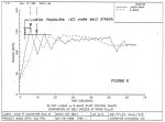
Figure E
Figure E illustrates the comparative belt tension peaks, where the linear ramp causes a 15% increase in belt stress.
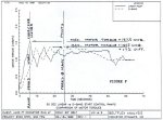
Figure F
Figure F illustrates a 17% increase in peak motor torque demand during starting.
Figure G
Figure G illustrates the higher T1/T2 ratio of the drive pulley that is more likely to cause drive pulley slippage on the belt.
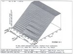
Figure H-1 |
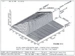
Figure H-2 |
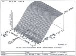
Figure J-1 |
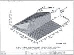
Figure J-2 |
Figures H and J illustrate three-dimensional graphic plot of the complete belt loop as the velocity and tension change in time for the linear and S-band respectively.
HORIZONTAL CURVE USAGE
Horizontal curve usage in the United States and by U.S. operators and owners overseas is bound to increase in the near future. More than a dozen new major installations in the U.S., U.K., Australia, RSA, and Europe have been commissioned in the last few years, or are now being commissioned. I have just completed the empty belt commissioning of the first 10 Km flite of a 20 Km system in Australia. The first flute was routed to minimize cut and fill, to reduce excessive belt undulation with added belt stresses and power demands being eliminated. The belt has a 4.5 Km (15,000 ft.) curved zone. The belt performed as predicted by our curve analysis theory and dynamic analysis. No idlers required adjustment in or outside the curves, although provisions were made for the possibility. The curved belt bath saved the client significant civil and mechanical expenses. I would recommend their use where difficult terrain can be negotiated, resulting in the elimination of transfer stations and excessive civil works, that may make the conveyor uneconomical.
TABLE 1: High Capacity / High Lift Conveyors
|
Mine Design |
Year | Capacity (T/H) |
Power (kW) |
Length (Km) |
Lift (m) |
Width (mm) |
Speed (m/s) |
|
| 1. | Thompson Creek (USA) Moly. | 1983 | 4100 | 2800 | 1.8 | 117 | 1524 | 3.3 |
| 2. | Island Copper (USA) Copper | 1985 | 4500 | 3000 | 0.9 | 250 | 1372 | 4.2 |
| 3. | Loveridge (Consol) (USA) Coal | 1985 | 2730 | 3000 | 0.9 | 250 | 1372 | 4.0 |
| 4. | Lornex (Canada) Copper | 1988 | 7000 | 3360 | 1.5 | 150 | 1500 | 4.4 |
| 5. | Bingham Canyon (USA) Copper | 1988 | 9100 | 4480 | 2.0 | 68 | 1829 | 4.7 |
| 6. | Chuquicamata (Chile) Copper | 1983 | 4900 | 5700 | 2.6 | 290 | 1800 | 4.5 |
| 7. | Palabora (RSA) Copper | 1988 | 6500 | 7050 | 1.1 | 290 | 1800 | 4.1 |
| 8. | Morenci (USA) Copper | 1989 | 9500 / 7500 | 3750 | 1.7 | 126 | 1524 | 4.7 |
TABLE 2: Overland Conveyors
|
Mine Design |
Year | Capacity (T/H) |
Power (kW) |
Length (Km) |
Lift (m) |
Width (mm) |
Speed (m/s) |
|
| 1. | M.I.C.A.R.E. (Mexico) Coal | 1980 | 900 | 1200 | 9.0 | -- | 900 | 4.6 |
| 2. | Quintette (Canada) Coal | 1983 | 2000 | -2600 | 7.2 | -524 | 1050 | 6.1 |
| 3. | Selby (UK) Coal | 1983 | 2500 | 10100 | 12.2 | 800 | 1300 | 8.4 |
| 4. | Bingham Canyon (USA) Copper | 1988 | 9100 | 4480 | 5.3 | -27 | 1829 | 4.7 |
| 5. | Channar (Australia) Iron | 1989 | 2200 | 2100 | 10.0 | -- | 1050 (H. Curve) |
4.1 |
| 6. | Kaltim Prima (Indonesia) Coal | 1991 | 2000 | 2000 | 13.0 | -- | 1000 | 5.3 |
| 7. | Morenci (USA) Copper | 1992 | 7300 | 4500 | 1.4 | -245 | 1524 | 4.1 |
Conveyor Dynamics, Inc. Recommended Limitations of Conventional Troughed Belt Conveyors
| ITEM | PRACTICAL LIMITS | WORLD RECORDS | |
| 1. | Width | 3.0 m (120 in.) | 6.0 m |
| 2. | Speed | 8 m/s (1575 FPM) | 8.4 m/s |
| 3. | Idler Pitch | 3.0 m (10 ft.) | 6.0 m |
| 4. | Single Flite Length | 26 km (85000 ft. / 20 mi.) No limit with booster drives |
13 km ( conventional belt) 20 km (sub-cap. Sahara) 30 km (Cable Belt) |
| 5. | Lift (surcharge limit) |
Uphill / Downhill 15 deg. / 12 deg. (unshielded) 18 deg. / 15 deg. (shielded) |
> 20deg. |
| 6. | Breaking Strength (cable) | > ST- 8000 N/m (feasible) | ST-7500 N/mm |
| 7. | Safety Factor | SF = 5.0: 1 (>5 yrs. life) SF = 4.0:1 (<5 yrs. life) SF = 3.0:1 (limit) |
4.5: 1 |
| 8. | Useful Strength (Operating Limits) |
8000 PIW (@ SF = 5:1) 9100 PIW (<5 yrs.) |
7300 PIW |
| 9. | Total Lift One Flite w/o intermediate drives |
900 m / 3000 ft. Coal 500 m / 1600 ft. Copper |
800 m (2600 ft.) |
![]()