L.K. Nordell, USA
Summary
Copper, iron and other hard rock mineral ores utilize the rock box principle to control the flow of primary crushed ore in the transfer chute, typically -200 mm open side setting. This concept minimizes the metal degradation of the chute liners and bottom surfaces, but does not protect the receiving belt from structural damage and accelerated Cover wear. The engineer specifies sufficient belt rubber cover thickness and proper rubber compounding to yield a respectable service life. With large tonnages, high belt speeds, and large sham rock, this may not be the best strategy. An alternative curved ore transfer chute concept has been developed by Conveyor Dynamics, Inc. in cooperation with the Palabora Mining Company. The curved chute controls the flow of ore placing it onto the receiving belt where the ores forward velocity approximates the belts speed, minimizing abrasive degradation, and where the ore's design impact pressure is below the belt cover's critical gouging drainage threshold. This curved chute concept shows significant promise in reducing:
- the need for large belt cover thickness,
- large steel cord filament diameters to resist breakage under rock impact,
- rip and puncture from metals, and
- spillage and its related damage at the transfer station.
1. Introduction
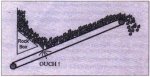
The Palabora Mining Company, located adjacent to Kruger National Park in South Africa, mines copper in an open-pit operation. In 1989. an in-pit 60 x 89 gyratory crusher, and incline tunnel conveyor were commissioned to haul primary crushed copper (-200 mm OSS), at 6,500 t/h, from in-pit to the surface auto mills and secondary crushers. The conveyor is inclined 16.5 degrees and transports the ore, with maximum lumps to 600 mm (60 kg), on an 1800 mm wide ST-6600 N/mm belt, 1,100 m long with a 300 m lift. A conventional rock box, Fig. 1. was designed to control the ore flow onto the incline conveyor from the belt feeder under the primary crusher. The incline belt top cover is 18 mm thick and is specified with an 'X' grade rubber according to DIN (abrasion value < 100 mm). After 3.5 years of operation, the top cover wore down till the tensile cords began to show through the 18 mm thick top cover. The original belt warranty was for 10 years.
Palabora requested the assistance of Conveyor Dynamics, Inc. (CDI) in developing an alternate means of controlling ore flow onto the belt which would significantly reduce the belt cover west. CDI developed a curved chute design for primary crushed hard rock applications under contract to Palabora. The curved chute was installed in April 1994, and the success of this installation is the topic of this paper.
2. Methods of Analysis
2.1 Historical
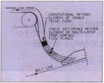
There are few engineering guidelines on chute design with large rock flow which focus on minimizing belt wear. Grizzlies may be the exception. They are rarely reliable. Elementary trajectory analysis is performed to locate baffle plates and rock boxes for impact and directional control, Experience has guided the wear plate specifications. In the published technical literature Roberts [1][2][3][4], and Scott [5] utilize single layer 'slug" flow instead of discretized layered flow shown in Fig. 2. Single layer flow does not provide the analytic structure to quantify the belt cover abrasion and gouging damage mechanisms in the impact region,
2.2 Modern
The physics of ore flow in a chute and onto a moving belt conveyor is a difficult technical field to portray accurately.
Solid ore flow must be treated with different constitutive laws than with fluid flow. The main differences are: (1) fluid flow resistance depends on the velocity gradient and is not dependent on changes in hydrostatic pressure, while (2) solid particle ore flow depends on coulomb friction and is dependent on changes in hydrostatic pressure (Normal Stress contact dependence). In the simplest model, the ore flow stream is considered to be homogeneous (no particle size distribution influence) and inelastic (non-yielding).
|
Fig 1. Ore flow over rock box onto slope belt |
Fig 2. Ore flow
simulation |
Ore chute flow must be treated with one surface free or unbounded. The principle follows the work of Chaudhry in open channel fluid flow [6]. Modem treatment of "open channel or free surface" flow utilizes the finite element form of meshing the surfaces into discrete bodies. The interface constitutive properties or laws between bodies layer by layer and within the bodies are then formulated.
Often simplifying assumptions are tried and tested to minimize the necessary complexity. The basic assumptions used to evaluate the curved chute concept are as follows:
- homogeneous flow - no particle size influence
- interlayer cohesive drag - linear hydrostatic dependence
- internal shear angle - simple material surcharge angle
- wall surface drag - wet and dry simple motion test on selected materials
- flow mesh -4 to 5 surface layers (up to 20 layers developed in model)
- flow characteristics:
- interlayer cohesive drag dependent on hydrostatic pressure for all contained flow in the channel
- free fall vertical velocity gradient between layers
- impact energy dissipation function from free fall
- centripetal frictional resistance in curvature
- viscoelastic impact onto belt surface
- inelastic interfaces between layers
- interlayer collision in conveying side walls
- drag on side walls and bottom dependent on hydrostatic surface pressure
Three methods of analysis were reviewed:
- finite element method (FEM) with moving frame of reference based on continuum mechanics
- finite difference method (FDM) - explicit scheme
- discrete element method (DEM), based on discontinuum mechanics
The FDM model was chosen because of its simple mathematical structure which could be formulated in a timely manner, The FEM model would require a special element construction and would require the use of slip planes which is too computer-intensive.
The DEM is a new and exciting field which is promising, but was also eliminated because of its computing time limitations (approximately 100 times greater than FDM), and the effort to adequately define the necessary properties.
Normal Stress yielding and deformation was not included in the model, This additional feature, which can be added along with other rheological properties, can extend the use of this tool into bins, bunkers, feeders, ore pass flow, stockpile stacking and reclaiming, tailing dams, embankment stability analysis, etc.
3. Analytic Procedure
The FDM model was developed to define a finite approximation solution to the three principle damage factors:
- Ore velocity gradient (rock-belt sliding) between ore layer in contact with belt, until ore reaches belt speed.
- Ore impact pressure magnitude along belt surface from initial point of impact until ore contact layer reaches belt speed.
- Product of ore velocity gradient and impact pressure until ore layer in contact with belt reaches belt speed to qualitatively assess abrasion and gouging damage by a relative comparison between the rock box and the curved chute.
Rock shape and size certainly influences the degree of damage. Our initial assumption excluded the difference between rock size and contact (stylus) attributes. It can be argued that the pressure, at point of contact, is independent of small rock impacting on top of big rock or big rock impacting on small rock.
Various FDM mesh schemes were used. The differences between contact forces on chute side wails, bottom surfaces, and onto belt became insignificant beyond four surface layers.
The model accuracy was verified by full scale prototype measurements of chute flow and model predictions. The measurements were taken from a report on a comprehensive U.S. confidential study on curved chutes conducted in 1966. Prediction of ore surface velocity, measured by high speed camera, was within 1% of the measured values over the full distance of ore flow in the experimental chute.
The ore drops over 3 m in the Palabora chute. Control of the rock impact force, velocity gradient on belt surface, and liner forces were all factored. Palabora uses a Score 27 high chromium (Brinnel +600 hardness) 100 mm thick cast liner.
The design philosophy is to place the ore stream in free fall and size chute curvature until a velocity is reached which will carry the ore onto the belt at half the velocity difference of the rock box concept. It is important to place the ore onto the belt as close vertically as possible to minimize free fall.
Trade off conditions must be evaluated in selecting the proper curvature. A greater drop height will result in a greater exit velocity, but the curve radius must then be reduced, which results in greeter damage to chute liners from the high impact and centripetal forces, The exit angle also is a critical factor. The chute would plug if the exit angle was increased to beat a right angle and parallel to the belt.
At the discharge from the belt feeder, the chute is 2,400 mm wide. while the belt entry width is only 1,100 mm wide. The ore can be consolidated while in free fall, or along its full chute length. or just prior to entry onto the belt. Our choice was the full length chute for consolidation transition, This provided superior theoretical flow values.
Combining the three-dimensional considerations of a fixed drop height, variable radius of curvature, variable ore exit angle, and ore stream width transition from 2,400mm to 1,100mm had to be evaluated with variations in wet and dry ore, and with the rock size influence on liner drag. Rock size and moisture variables on the drag coefficients were measured by simple incline plane tests with the nominated liner plate. The tests measured the angle required to keep the rock in motion once motion was initiated.
4. Results
4.1 Theoretical
Fig. 3 illustrates the theoretical analysis results on a conventional rock box. The flow stream is presented in a velocity gradient format. The ore stream slips over the belt feeder head pulley; goes into free fall, then reaches maximum velocity at the point of impact with the rock box ore bed: after slowing from the impact, the ore again picks up speed sliding down the rock surfaces at its repose angle until it leaves the chute. Upon leaving the chute, the ore stream direction is significantly changed by the gravitational force prior to impacting the belt. The ore velocity is reduced to less than 2 m/s. from over 5m/s, at the point of impact. Once the ore impacts the belt it takes approximately 2 m to accelerate the ore bottom layer to belt speed. The top layer of ore riding on the-belt takes approximately 4 m to reach belt speed. The interlayer velocity difference, if large, may lead to additional damaging turbulence. This effect was not considered in the damage assessment. Element meshing in the impact region is greater than in the general flow stream.
Fig. 4 illustrates the recommended curved chute analysis using the velocity gradient format. Note, the free fall distance is reduced at the point of impact with chute bottom liner, The ore impact velocity is also lower at the Initial chute contact point, but the maximum ore stream velocity is greater. Therefore, the main damage to the liner material is abrasion, not impact. The Score 27 material was selected over manganese liner for this reason, The ore in contact with the belt reaches the belt speed in 1.5 m.
Note: in Figs. 3 and 4 an accurate material trajectory is also illustrated.
Figs. 5a, b and c are graphic illustrations comparing the rock box and curved chute theoretical velocity gradient, pressure gradient, and velocity-pressure multiple differences at the ore-belt contact surface. The curved chute initial contact velocity gradient is approximately 60% of the rock box value. The rock box velocity gradient integrated over the belt sliding distance is approximately twice the curved chute. This is one indication of the expected reduction in abrasive wear. The rock box pressure gradient, at the point of impact, is 40% more than the curved chute, Given that impact damage is a simple logarithmic function, then the curved chute should reduce the gouging damage by more than 50%. There is a critical tensile force which causes the rubber to fracture. If the rock impact force (pressure) is below the critical value, then the tip of the rock (stylus) will not cut into the belt, The cutting action, coupled with the ore-be velocity difference produces a tearing action on the belt surface, The rock box combined velocity-pressure multiple value is more than twice the curved chute at the point of impact.
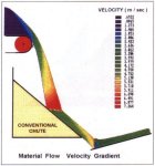
Fig 3. Rock box ore flow path
and velocity gradient from primary
crusher belt feeder to 15.5 slope conveyor
The Palabora belt surface damage was predominantly gouging or pitting. The wear pattern appeared to be very non-linear with time. Only abrasive wear appears in the initial field measurements after six months of operation. The pitting does not show up as a measured wear until the collection of pits or gouges coalesce, or come together. Gouging will accelerate as the belt cover thickness is reduced. When abrasion and gouging loss are plotted over time, the dominance of gouging produces a convex plot to the 'X" axis.
4.2 Field Evaluation
Palabora commissioned the curve chute, illustrated in Pig. 6, and a new belt, in April 1994. I inspected the belt six months after the new chute became operational. No pitting or gouging damage was evident. The belt surface was smooth. Placement of a straight edge across the belt width did not indicate any local wear depressions. Two small 150 mm slightly roughened regions were found and are attributed to ore turbulence caused by small rail bars, both on the side walls, placed in the line of flow, near the chute exit, by the maintenance staff, I believe these are supposed to act like ore stream centering devices, usually found in rock boxes. They are targeted for removal. The two small roughened zones appear to have less than 2 mm of wear, Elsewhere, no more than 1 mm was worn.
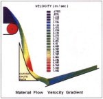
Fig 4. Curved chute ore flow
path and velocity gradient from primary
crusher belt feeder to 15.5 slope conveyor
|
Fig 5a. Velocity
difference of ore on belt |
Fig 5b. Impact
pressure of ore on belt |
|
Fig 5c. Velocity
difference x impact pressure of ore on belt |
|
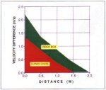

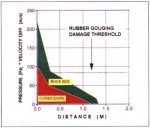
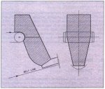
Fig 6. Curved chute arrangement at Palabora
5. Future
Plow modeling and soil mechanics problems, in general, will utilize discrete element methods (DEM) in the future. This work was pioneered by Peter Cundall [7] of the USA about 20 years ago. The first U.S. DEM conference was held in August 1989 [8] DEM can model slip and rotation between elements, dilation of surfaces, irregular body contact, contact yielding, large and small strain, multi-phase flow (gas, liquid and solid), thermodynamics, etc, The constitutive laws and rheological coupling models are being developed in many universities in the USA, Japan. and Europe. Exploitation of this new science will require advances in computer power (parallel processing) and numerical techniques.
The Colorado School of Mines Geomechanics Research Center is a leader in this field, They have kindly provided the following commentary and examples:
The discrete element method is a numerical technique especially well suited for modeling bulk material flow problems of a general nature. For example, in a discrete element model it is possible to define the bulk material as a system of general shaped bodies with realistic collision mechanics laws for body/body and body/boundary contacts with a complex system of boundary constraints. This type of modeling can provide detailed information to engineers in the following areas: material flow behavior, forces induced by the bulk material on conveyors, chutes and transfer points between conveyors.
Fig. 7 shows how the discrete element technique can be used to simulate the flow of particulate media through complex boundary geometries. Fig. 8 illustrates the "hydraulic jump# like flow behavior of particulate media flowing over a discontinuous step in an open channel. This physical phenomenon is similar to that exhibited by water flowing in a similar situation.
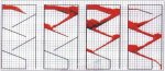
Fig 7. Material flowing over cascading boundaries
6. Conclusion
Curved chutes are not new .n coal and grain. They are new in hard rock. The Palabora project shows they can be made to work effectively in hard rock, The concept provides benefits in belt cover wear and is equally significant in belt puncture and rip protection. Transfer station spillage is reduced. Control is improved and degradation of friable materials can be significantly reduced.
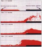
Fig 8. Particulate material flowing in an open channel
Acknowledgments
The author thanks the Palabora Mining Company for this opportunity and for their courage in undertaking this difficult project.
Thanks are due to Prof. Graham Mustoe, graduate student Andrew Hustrulid, and the support team of research students of the Colorado School of Mines Geomechanics Research Center for our recent discussions of their illustrated work.
References
[1] Roberts, AW,: Flow of bulk solids through transfer chutes of variable geometry and profile; bulk solids handling vol. 1 (1981) No.4, pp. 715-727.
[2] Roberts, AW. and Ooms. M.: Some aspects of surface friction, adhesion and wear in gravity flow, handling and belt conveying of bulk solids; BELTCON 3, Int'l Material Handling Conference, pp. 1-43, Sept. 1985.
[3] Roberts, AW.: Influence of surface friction and adhesion on chute design and handling plant performance; TUNRA, Basic Principles of Bulk Solids Storage, flow and Handling. Chapter 6. Sept. l992.
[4] Roberts, AW,: Transfer chute performance and design; TUNRA, Basic Principles of Bulk Solids Storage, Row and Handling, Chapter 18. Sept. 1992,
[5] Scott, OJ.: Conveyor transfer chute design: TUNRA, Basic Principles of Bulk Solids Storage, Row and handling, Chapter 11, Sept. 1992.
[6] Chaudhry, MH.: Open-channel Flow: Prentice Hall, Englewood Cliffs, New Jersey, 1993.
[7] Cundall, PA, and Strack, ODL,: Distinct element method as a tool for research in granular media; Report to NSF, Grant ENG 76-20771, Univ. of Minnesota, 1979.
[8] Mustoe, G., Henriksen, M., and Huttelmaier, HP., (eds.): First US Conference on Discrete Element Methods, Golden, Colorado. August 1989.