4. viscoelasticity (extension)
+F = H1 x
viscoelasticity (relaxation)
-F = H2 x
H1 = (1/K2 + 1/β1)-1
H2 = (1/K2 + 1/β2)-1
5. St. Venant Impedance
F = C = f (coulomb drag)
6. belt axial beam response
F = G = f (belt geometry)
Superimposed on these forces are the reactions or responses of the driving or braking devices and the response of the take-up system. Each of these six force functions act somewhat independently.
The basic rheological elements noted above are illustrated in Figs. 1-6.
Fig. 1 illustrates elemental substances which obey Hooke's Law such as the elastic modulus of the bell's tensile members. Their functional properties may be non-linear In nature. For the system's rheological model, the elastic modulus is defined by the matrix vector K1.
![]()
Fig. 1: Hookean element (K1)
Fig. 2 illustrates viscous impedance through the analogy of a dashpot. This is sometimes referred toe a Newtonian element. The resistance to motion is belt velocity dependent. Idler, pulley, gearbox, and motor bearing losses, gearbox churning losses, material trampling losses, and motor wind-age losses make up a major portion of these bases. This rheological element may be non-linear in nature. It is defined by the matrix vector V.
![]()
Fig. 2: Newtonian element (V)
Fig. 3 illustrates a Maxwell element. By connecting the spring and dashpot in series, part of the viscoelastic deformation can be modeled. The Maxwell element Is represented by the matrix vector H(±). Axial wave motion, in the belt, generates hysteresis losses, characterizing polymeric relaxation and retardation deformation modes. The model allows the spring constant to be time dependent. As the localized reaction time becomes shorter, the spring becomes stiffer. The Maxwell element dashpot also acts in parallel with the spring element K1 of Fig. 1 to form a Kelvin or Voigt element. Polymers such as rubber, nylon, and polyester can be rheologically simulated with the Maxwell/Kelvin analogy.
The Kelvin element closely models the vertical elastic support of the idler to the belt interface as a moving load. This Is a major property of the rolling friction (indention loss).
![]()
Fig. 3: Maxwell element (H)
Fig. 4 illustrates a St. Venant element, labeled as matrix vector C. This element models the transitional static to dynamic friction. This friction is analogous to Coulomb friction of a sliding block on a dry surface.
The transitional friction or "breakaway" friction is caused by:
- overcoming the Idler imprint resistance due to the belt cover deformation.
- idler seal adhesion,
- redistribution of settled grease in the idler bearing cavity;
- belt catenary sag deformation, between idler supports, set by the rubber's relaxation.
Environmental temperature variation can substantially after the magnitude of this value. For dynamic models, this type of friction is sometimes referred to as solid damping.
![]()
Fig. 4: St. Venant element (C)
Fig. 5 illustrates the variable axial geometric stiffness produced by the vertical acting forces on the belt's cross-section between idlers. The vertical forces are held In equilibrium by the belt's axial tension. Conveyors of different belt construction (fabric; steel), of different material loading, of differing idler spacing and trough shape configuration, after the effective axial stiffness. This results in an apparent reduction in the belt's elastic modulus. The representation of this element is by the matrix vector G.
![]()
Fig. 5: CDI geometric beam element (G)
Fig. 6 illustrates the five element composite rheological model of Conveyor Dynamics, Inc. (CDI), including all features described in Figs. 1 - 5.
![]()
Fig. 6: CDI five-element composite model
Dynamic simulation of the complete conveyor rotating system Is accomplished by dividing the belt Into a specified series of finite elements as shown in Fig. 7. Each finite element has a lumped mass and an individual rheological spring response structure given In Fig. 6.
![]()
Fig. 7: Lump-mass spring-dampened finite element model
The equation of motion, which describes the transient force-displacement relationship, is given in the form:
| F(t) = M | .. | + K1x + V | . | + H( | . | , x) + C(x, F(t)) + G(x) |
| x | x | x |
F(t) represents the force applied on an element at time t. The equation is given as the matrix of (n) finite elements with the equilibrium condition acting on each element.
All transient analysis must start from known boundary conditions. The assumed boundary condition for this analysis is the steady-state running condition (t = ∞). The steady-state running forces are derived from the classical belt tension calculations given in various texts [6-9] or more advanced references [1O-14J. From the steady-state equilibrium boundary condition, the actions of stopping (forced braking or free drift) can be administered. Upon reaching the new boundary condition, t = 0, starting actions can then be studied. From t = 0, many forms of starting and stopping can be modelled, such as:
- Across-the-line Asynchronous Squirrel Cage Motors
- Wound Rotor Motors with Multiple-Step Resistor Starting
- Wound Rotor Motors with Reactor Control Starting
- Fluid Couplings with Constant or Delay Filling
- Fluid Couplings with Various Filling Programs
- Eddy Current Couplings and Brakes
- Solid State SCR. Inverter and DC Ramp Controls
- Caliper-Disk Brakes, et al.
The properties of control circuits can be modelled to include the actions of:
- Speed Ramp controller logic functions including:
dS/dt: velocity-time ramping
dV/dt: acceleration ramping separately or in conjunction with dS/dt control
d²V/dt² jerk control superimposed on basic ramp - Take-up slewing control and load cell functions
- Multiple-pulley drive load sharing logic and interactions regardless of location along carry or return belt strand, including intermediate drive concepts
- Tachometer feedback loop delay sensitivities
- White noise smoothing control (e.g., generated by high amplitude forcing functions on high modulus belts -harsh braking, etc.)
The theory of damped mechanical vibration with multiple degrees of freedom, required for finite element modelling, is surveyed in references [15] and [16]. Composite rheological modelling is presented well in reference [17]. The nature of polymeric behavior is given advanced treatment in reference [18]: Chapter 7, Viscoelastic Models, and Chapter 9. Viscoelasticity in Non-Metals.
4. Case Studies
A brief review of some case studies is presented to illustrate the various types of problems encountered. The studies are not preferentially ordered by design importance or chronology.
- Study No.1 is an 8,150 ft long conveyor built in 1965 (reference Fig. 8). The conveyor is basically horizontal, transporting over 8,000 short t/h with a belt speed of 930 ft/mm (41 m/s). When the fully loaded belt was shutdown, a reaction wave would impact the gravity take-up assembly with a force over twice its steady state load (Fig. 12). The conveyor was instrumented with five speed sensors: before the drive, at the head and tall, along the carry strand above the drive, and before the take-up. Instruments measured the take-up load, take-up displacement, power readings, and tonnage.
- Study No.2 illustrates the startup response of a 30,000ft (9.15 km) long horizontal belt conveyor. The conveyor transports 900 metric t/h of coal at 725 ft/mm (31 m/s). The conveyor is equipped with two 600 HP (373 kW) motors on the head pulley and one 500 HP motor on the tall pulley. No telemetry is provided between the drives. Fixed and slewing take-up assemblies were studied.
![]()
Fig. 8: Geometric profile of Study No. 1
Fig. 9 shows a plot of the field measured velocity and of the BELTFLEX predicted velocity versus time curves at point A, just prior to the drive location. Note the mile long section of return side belt that is under high stress. A very fast velocity decay occurs for the first 2.5 seconds. The large velocity gradient or shock wave is propagated from the drive station toward the head, in a reverse direction to the normal belt travel.
![]()
Fig 9: Velocity vs. speed at shutdown - Point A.
Fig. 10, at point B, shows the velocity-time plot with a 3.72 second delay before the advancing wave acts on this location. The predicted and measured values of the advancing wave time are in close agreement. Independently, the time period for the wave to react at point B was computed from a wave velocity equation submitted by Harrison [5]:
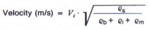
The velocity wave front was computed to travel at approximately 4,760 ft/sec (1,450 m/s) on the belt empty return strand and at 1,925 ft/sec (590 m/s) over the fully loaded carry strand.
![]()
Fig. 10: Velocity vs. speed at shutdown - Point B
Fig. 11, at point C, shows the velocity wave Impacting the take-up zone 5.86 seconds after shutdown. The wave has travelled over l6,000ft (4.880m.). Although points A and C are in close proximity, little initial wave reaction moved with the direction of normal belt travel. The BELTFLEX predicted reaction time, the field measured time, and the time derived by Harrison's wave velocity equation are in very close agreement.
![]()
Fig. 11: Velocity vs. speed at shutdown - Point C
Fig. 12 shows the measured versus predicted take-up force response. The gravity take-up assembly was equipped with a motion retarder that applied a 6,000 lbs (2,720 kgf) drag on take-up movement in either direction of travel. The retarder was installed to reduce excessive take-up motion. High transient forces continued to break down the retarder assembly. Note, approximately 16 seconds after shutdown a large transient spike is recorded. The spike is more than double the steady-state force.
![]()
Fig. 12: Take-up force vs. time with retarder active
Fig. 13 shows the predicted belt tension versus time response at point B. Note the large oscillating wave forces that exceed the steady-state force.
This study is presented here to illustrate, from field measurements, the heretofore unpredictable nature of large transient effects which may occur at shutdown. Very often the engineer concentrates on the methods of controlled starting and gives little attention to the forces generated during stopping. From the experience on CDI projects, from field data and on case studies, stopping of large high modulus belt is potentially more damaging, is less controllable, and is more difficult to assess than the action of starting. The belt's internally stored strain energy reacts with a higher specific impulse than can be generated by the drive system.
![]()
Fig. 13: Predicted belt tension response vs. time - Point B
Fig. 14 shows the BELTFLEX startup velocity versus time plot of the head and tail drive stations. The conveyor Is equipped with a slow acting 0.025m/s winching take-up. The engineer's rigid-body acceleration calculations showed that the head drive slack side traction force, required for normal running, would be inadequate for starting. The take-up force, prior to starting, was then pre-stressed to 135% of the running value The head drive applied increasing steps of torque to a maximum of 150% of its motor nameplate. The tail drive was programmed to engage upon sensing belt line motion. The tail drive was set to pull 80% of its nameplate rating during the starting phase. The BELTFLEX plot shows that 15 seconds after the heed drive is powered the tail pulley responds. The plot shows a velocity undulation at 15 second intervals for both head and tail stations. The large velocity swings are caused initially by a large strain-energy wave that was Imparted to the belt by the head drive. When the head drive applied power to the belt, the belt carry strand was stretched, increasing its strain energy, as tension was applied. The return strand tension and strain energy were simultaneously dropping: 1) from the stretched carry strand belt fed by the head drive and, 2) lack of take-up displacement. The tractive tension ratio across the head pulley became unstable and, from the calculations, showed that excessive pulley slippage would occur. This detrimental characteristic was even more pronounced at the tail drive. The analysis showed that the design was not adequate. The take-up slewing response would have to be increased by more than a factor of ten or the acceleration time would have to be extended for many minutes. The engineer altered the design by increasing the take-up response to more than 0.3 m/s.
![]()
Fig. 14: Start-up with fixed take-up velocity vs. time - Study No. 2
Fig. 15 shows the velocity versus time plot of the engineer's modifications. The slewing take-up response rate was set to approximately match the accumulative belt stretch from the carry strand. It can be seen that the large velocity undulations have been significantly reduced. The study indicated that this system should provide an adequate design. Subsequently, the conveyor was built and commissioned. It has been operational for more than one year.
![]()
Fig. 15: Start-up with slewing take-up velocity vs. time - Study No. 2
5. Discussion
A method of modelling the true elasto-mechanical dynamic behavior of the belt has been introduced, together with a brief discussion on two case studies. A number of studies have been completed which provide Insight into the many aspects of conveyor design, insight which is only discernible through elastic-transient modelling. The BELTFLEX model, used for these studies, utilizes a non-linear finite element approach. It is based on the discrete time-integration method of solving the second order differential equation of wave mechanics in viscoelastic solids.
References
- Richolm, I., 'Dynamic Behavior of Belt Conveyors During Startup", Bergbautechnik Vol. 20 (1970) pp. 138-144
- Lai, J., and Chen, C., "Vibration and Dynamic Stability of an Axially Moving Belt", ASME preprint No. 71-Vibr-31, (1971)
- Rao, K.R.M., "Computer Study of Starting Phenomenon of a Conveyor". Technological Inst. Kanpur, India, J. Inst. Eng. Mining Metal Div. V. 53 Part MM, pp. 109-113. July 1973.
- Funke, H., "The Dynamic Stress of Conveyor Belt Systems When String and Stopping", Braunkohle Vol. 26 (1974), No. 3, pp. 64-73
- Harrison. A., "Transient Stresses in Long Conveyor Belts", CSIRO Division of Applied Physics, Sydney, Australia, Report (1981).
- Goodyear Tire & Rubber Co-, "Handbook of Conveyor and Elevator Belting", 1976
- Conveyor Equipment Manufacturers Association (USA), "Belt Conveyors for Bulk Materials", Second Edition, 1979
- International Standard ISO 5048, "Continuous Mechanical Handling Equipment", First Edition (1979)
- DIN 22101, "Belt Conveyors for Bulk Materials', 1982
- Schwarz, F., "Untersuchungen zum Eindruckrollwiderstand zwischen Frdergut und Tragrolle", Dissertation, Technical University Hannover, 1966
- Behrends. U., "Untersuchungen zum Walkwiderstand schwerer Frderbandanlagen". Dissertation, Technical University Hannover, 1987
- Spaan, C., "The Indentation Resistance of Belt Conveyors", Delft Technical University, Dept. of Mech. Eng. WTHD Nr. 103, Jan. 1978.
- Spaan. C., "The Flexure Resistance of Belt Conveyors". Delft technical University, Dept. of Mech. Eng. WTHD Nr. 117, Sept. 1979.
- Jonkers, C., "The Indention Rolling Resistance of Belt Conveyors". Frdern und Heben, Vol. 30 (1980) pp. 312-318
- Pastel, E.C., and Leckie, F.A., "Matrix Methods in Elasto-Mechanics", McGraw-Hill, 1963
- Timoshenko. S., Young, D.H., and Weaver, W. "Vibration Problems in Engineering", John Wiley & Sons, 1974.
- Flugge, W., "Viscoelasticity", Second Edition Revised, Springer-Verlag, 1975
- Gittus. J., "Creep Viscoelasticity, and Creep Fracture in Solids", John Wiley & Sons, 1975