Basics
Functional Description
A number of different features and components are found on pocket belt conveyors. The inclusion of some of these components depends on the particular application for example, whether or not the conveyor is totally enclosed.
The following details are however generally found on pocket belt conveyors.
A. The Conveyor
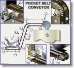
As with all conveyors, the pocket conveyor comprises a loading station (1) a conveying section (2) and a discharge station (3).
Material (4) is loaded onto the tail-end of the conveyor via a loading chute and skirts (5). The loading section is usually horizontal although inclined loading stations of up to 10 degrees are used periodically.
Product drops into the various 'pockets' or compartments and is accelerated to belt speed. The length of this loading station depends on a number of factors (see 'Loading Stations' in 'Design Guidelines and Standards') however typically, the loading section is between 2,5m and 5,0m in length. Single roll impact idlers (6) support the belt at the loading station. From the loading point the belt is inclined to the desired angle (7), up to 90 degrees. This is achieved by installing a pair of disc-type deflection pulleys (8) above the belt, which engage the base belt and, on larger conveyors, the top of the sidewalls.
Material slumps down into each pocket as it negotiates the transition from horizontal to inclined conveying. Along this inclined section (2) the belt is supported on a series of flat idlers (9) at intervals to suit the inclination of the belt (fewer on steeper belts) and to provide adequate support.
At the top of the incline of the belt negotiates a second vertical curve (10) to horizontal. Due to the centrifugal force which could throw the product out of the pockets, the large bend radius required is achieved by a number of adjustable flat rolls (11).
From this deflection point the horizontal belt is supported on the flat idlers (9) up to the head/discharge pulley (12), where the material is discharged from the conveyor via the head chute (13) into the receiving conveyor / silo / etc. (14). This drive pulley is continuous (a drum) and the shell is usually lagged.
The return belt passes under a rapping idler (15), which assists in cleaning residual material off of the belt before the belt leaves the discharge chute. Material carryover on pocket-type belt conveyors is historically a problem. A number of techniques are available however, to improve belt cleaning and/or deal with spillage - refer to 'Belt Cleaning' in 'Design Guidelines'.
The return belt is supported on either edge by means of finger rolls (16) spaced at suitable intervals along the horizontal and inclined sections. At the top (17) and bottom (18) deflection points the belt is supported on pulleys. The top deflection point (17) comprises a pair of disc-type pulleys while the lower deflection pulley (18) engages the smooth surface of the belt and is therefore a drum pulley. The shell is not usually lagged.
Finally, at the tail of the conveyor, the belt is supported on a drum-type screw take-up pulley (19), which is adjustable to acheive the required belt tension.
B. The Belt
The pocket conveyor belt itself comprises a number of different applications and capacities.
Examples of generic features are provided below.
The belt comprises three main components as identified in the introduction of this section namely, the base belt, sidewalls and cleats or flights.
In terms of a belts' functional description, the base (1) is a cross-stabilized belt meaning that the belt is rigid across its width but flexible longitudinally. The base belt selection criteria include the belt tension, the belt width and correct selection of the belts' covers to suit the application.
Two sidewalls (2) are hot vulcanised onto the base belt and form the side panels of the conveyor, preventing material from slipping off the cleats. The sidewalls are convoluted and reinforced. The convolutions enable the belt to negotiate convex and concave radii imposed by the various pulleys. The design of the sidewalls ensures that minimal material is 'trapped' by the sidewalls and thus maximum cleanliness on the conveyor is achieved. The height of the sidewalls is a function of the capacity of the belt and depth / height of the cleats.
Cleats (3) are also hot vulcanised onto the base belt. The shape, width, frequency and height of the cleats are determined during the design process. Factors affecting selection of cleats include the capacity of product to be conveyed, the materials' bulk density, particle size and the desired angle of inclination of the belt. These factors also determine the pitch or frequency of the cleats on the belt.
The shape of the cleats fitted to a belt is also important in the design process. As has been indicated above, factors affecting the selection of cleats include: volumetric capacity, inclination and particle size.
Examples of different cleat shapes are shown adjacent.
