Bearing Housings
SKF
Bearing housings fitted with rolling bearings are economic, replaceable bearing units and require little maintenance.
SKF bearing housings are made of cast iron (certain plummer block housings are available in spheroidal graphite cast iron). The bearing seating of the housings is machined to tolerances such that a loose fit of the bearing outer ring is ensured, and in most cases the seating width is such that the bearing has axial freedom. Thus dimensional inaccuracies, slight positioning errors in mounting and thermal elongation of the shaft can be accommodated in the housing itself. Axial location of the bearing is achieved by employing the location rings specified in the housing tables. The figures in the locating ring designations indicate the approximate width and diameter of the ring. If only one ring is to be used with a bearing having an adapter sleeve, the ring should be positioned on the same side of the bearing as the lock nut; the bearing is then displaced from its central position in the housing by a distance equal to half the locating ring width. If two locating rings are used, one ring should be placed at each side of the bearing. When ordering, the number of locating rings required and their designation(s) should be stated.
SKF bearing housings are always supplied complete with seals. V-ring seals, felt seals (felt strips unless otherwise stated) or labyrinth seals are delivered with the housings as specified in the tables arid need not be ordered separately. V-ring seals are suitable for peripheral speeds of up to 12 m/s and operating temperatures of -40 to +100 deg. C. Felt seals are normally employed for peripheral speeds of up to 4 m/s and temperatures of up to + 100 deg. C. Before using felt strips, they should be soaked in hot cii for a few minutes. Labyrinth seals are universally applicable and not subject to wear.
SKF bearing housings are primarily intended for grease lubrication. In the majority of cases it is sufficient to charge the housings with grease on mounting and to replace this grease periodically when carrying out inspections. Plummer block housings have no provision for relubrication since used grease can be easily replaced once the housing cap has been removed. It shorter relubrication intervals are required a hole may be drilled and tapped to take a grease nipple or Supply line, the position is either marked or indicated by a boss.
For more detailed information regarding sealing arrangements, protective collars and bearing locating rings see cM/0900/PB1 -A
Plummer blocks
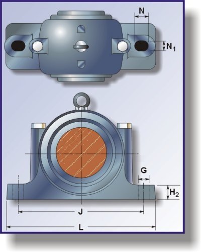
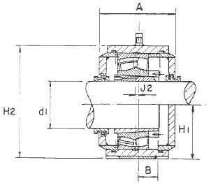
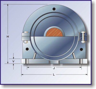
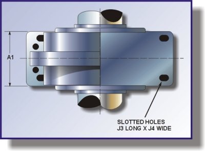
Plummer blocks are designed for use with self-aligning ball bearings and spherical roller bearings; the bearing may either have a tapered bore and be mounted on an adapter sleeve or may have a cylindrical bore. The elongated bolt holes in the housing base permit slight adjustments to the position of the plummer block to be made during mounting. The majority of housings are fitted with dowel pins to ensure correct location of the associated caps and bases, which are not interchangeable.
Plummer blocks are designed to accom-modate loads acting at right angles to the base. If the direction of load is not perpendicular to the base care should be taken to see that the housing, cap bolts and holding down bolts have sufficient strength to carry the loads involved. Approximate values for the breaking load for the housings and the yield point for the cap bolts are given in the tables on pages 391 to 393. To obtain the permissible load, the values are divided by a factor selected with regard to safety requirements. For general engineering pur-poses a safety factor of 6 is generally applied for the housings and a factor of 3 for the bolts.
SKF manufacture three different types of plummer block housings: SNA. SN and SD. SNA and SN plummer blocks are designed for use with bearings on adapter sleeves or with cylindrical bore. The housings of SNA plummer blocks are identical for both types of bearings, but are combined with different seals, whereas different housings are used for SN plummer blocks depending on whether the bearing Is to be mounted on an adapter sleeve or has a cylindrical bore. SD plummer blocks are for USS with bearings mounted on adapter sleeves.
Plummer blocks for bearings with adapter sleeve
SNA plummer blocks of series SNA 5 and SNA 6 can be supplied with V-ring seals (suffix TA), felt seals (suffix TC) or a seal set comprising one V-ring seal and one end cover with bonded rubber lip (suffix ATA) as standard. The seal set with end cover should be selected when bearings are to be mounted at the end of a shaft.
The V-ring seals Consist of a V-ring and a sheet steel washer, which has been treated to prevent corrosion. The V-ring is mounted on the shaft and seals against the washer, which is mounted in a groove in the housing. The washer has a bonded rubber lip and seals against the housing. The felt seals are ready to mount and consist of oiled felt inserted in a light alloy ring supplied in two halves. These are positioned in the seal grooves in the housing after first inserting a rubber 0-ring (also in halves). This provides adequate sealing between the housing and the ring halves and also prevents the felt seals from rotating.
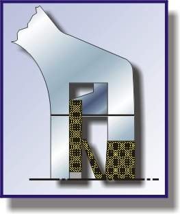
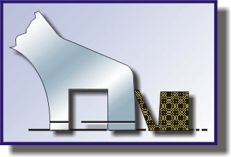
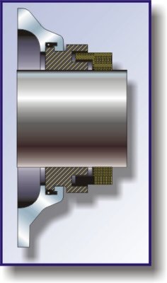
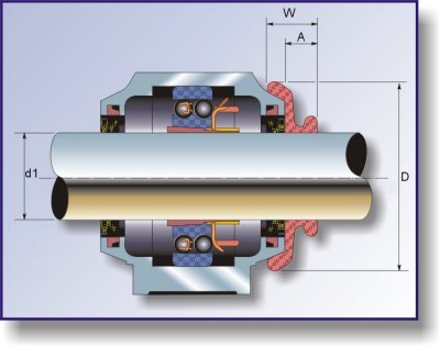
For exacting operating conditions, the V-ring and felt seals of housings SNA 505 to SNA 518 and SNA 605 to SNA 615 may be supplemented by a light alloy collar (see adjacent illustration), a standard component manufactured by SKF. The collar prevents the seals from becoming damaged and also enhances their sealing effect. The bore diameter tolerance is H10. The collar is designated TSNA B, e.g.: TSNA505B.
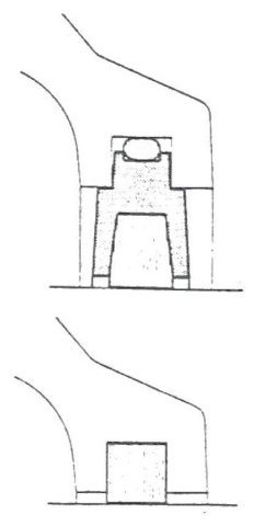
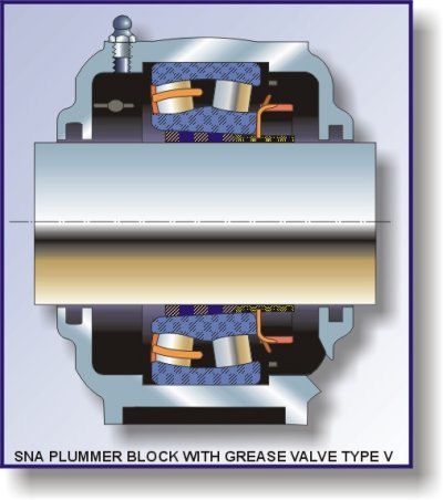
If frequent relubrication is required, housings fitted with V-ring seals should be selected (suffix TA). Excess grease can escape from the housing past the up of the V-ring and the risk of hot running because of over-lubrication is reduced. The efficiency o relubrication can be much improved by mounting an extra perforated V-ring inboard of the V-ring seal washer at the side where grease is applied so that grease can Only leave the housing at the opposite side. Housings of series SNA Sand SNA 6 with V-ring seals are therefore available complete with an extra V-ring, grease nipple and splash plate which covers a sector of just over 1800; see adjacent illustration. It should be noted that, where possible, grease should be supplied to housings with these additional features (suffix TAV, e.g. SNA51OTAV) on the side away from the lock nut.
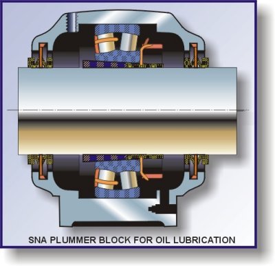
Housings with V-ring seals can be adapted for oil lubrication; see adjacent illustration. It is necessary to drill entry and exit holes for the oil and to supplement the seals. The holes should be drilled one at each side of the bearing so that oil must pass through it. Good sealing is obtained if an extra V-ring is mounted at each side of the housing in an inboard position with its lip against the steel washer: the extra V-rings should be of the perforated type. At peripheral speeds in excess of 7 m/s it may be necessary to locate the V-ring axially. If a wide bearing is used, the steel washer should be turned, for reasons of space, so that its rubber lip faces inwards.
SNA plummet blocks are a development of the SN plummet blocks; the dimensions of both SNA and SN housings follow ISO/P 113 and the housings of series SNA S aria SNA 6 are interchangeable with those of SN Sand SN 6, respectively.
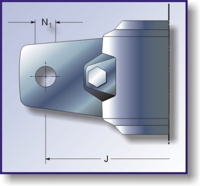
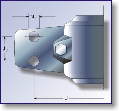
For special purposes where housings of particularly high strength are required, a standard range of housings from size 511-609 is available made of spheroidal graphite cast iron. These housings carry the designation prefix SSNAD, e.g. SSNAD 511 TA. With regard to the strength, please refer to page 391. The foot is solid and without bolt holes. These should be drilled according to the instructions given in the adjacent table. SSNAD and SNA housings are otherwise identical and the same bearings and accessories may be used.
Housing without seals
Dimensions mm
For two holes
For four holes
Designation
J
N1
J1
J2
N2
SSNAD 511-609
210
18
200
35
15
SSNAD 512-610
210
18
200
35
15
SSNAD 513-611
230
18
220
40
15
SSNAD 515-612
230
18
220
40
15
SSNAD 516-613
260
22
250
50
15
SSNAD 517
260
22
250
50
15
SSNAD 518-615
290
22
280
50
18
SSNAD 529-616
290
22
280
50
18
SSNAD 520-617
320
26
300
60
18
SSNAD 522-619
350
26
320
70
18
SSNAD 524-620
350
26
330
70
18
SSNAD 526
380
28
370
70
22
SSNAD 528
420
35
400
80
26
SSNAD 530
450
35
430
90
26
SSNAD 532
470
35
450
90
26
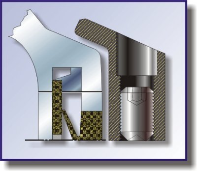
SN plummer blocks of series SN 5 and SN 6 are coupled with felt seals only. End covers for housings to be mounted at shaft ends are available; further details are available on request. For arrangements requiring frequent relubrication, housings with grease valves are available, see adjacent illustration. The housing dimensions are in accordance with ISO/R 113. The bearing seating is machined to tolerance H7.
SD plummer blocks of series SD 31 TS are designed to take large spherical roller bear-ings or Series 231 C. The housings are fitted with labyrinth rings. These have a clearance titan the chat, but a rubber O-ring inserted between the ring and the shaft ensures that the ring rotates with the shaft and also permits slight axial displacements caused by thermal changes in shaft length. Housings for shaft ends are supplied with an end cover instead of one of the labyrinth rings; further details are available on request. The bearing seating is machine to tolerance H8.
SD plummer blocks can be relubricated. The plug in the lubrication d at in the housing base can b replaced by a grease nipple. The grease penetrates the bearing via the lubrication groove and three holes in the outer ring (VJ33 feature). The housings are also suitable for oil lubrication. Bosses indicate where holes can be drilled in the base and cap for entry and exit of the oil and also to take an oil level gauge and a drain plug. Where circulating oil lubrication is used, the supply may be connected to the lubrication duct in the housing base.
Plummet blocks for bearings with cylindrical bore
SNA plummer blocks of series SNA 2 and SNA 3 are supplied with V-ring seals (suffix TA); those of series SNA 2 up to and including size l8with felt seals (suffix TC). If the housing is to be placed at the end of the shaft, the outer seal may be replaced by an end cover with bonded rubber lip: the designa-tions are given in the housing tables. The V-ring seals comprise a V-ring and a sheet steel washer with protective coating and bonded rubber lip. For housings SNA205 to SNA218 however, the V-ring seals do not include the washer, since the V-ring lips seal directly against the housing, the side faces of the housing being machined. The felt seals consist of felt strips. Regarding oil lubrica-tion please refer to page 386.
SNA plummer blocks are a development of the SN plummet blocks; the dimensions of both SNA and SN housings follow ISOIR 113 and the housings of series SNA 2 and SNA 3 are interchangeable with those of series SN 2 and SN 3, respectively. The SNA housings have much greater strength, however: see pages 391 and 392. Where even greater strength is required. SSNAD housings, described on page 387, can be supplied. The bearing seating is machined to tolerance H8.
SN plummet blocks of series SN 2 and SN 3 are supplied with felt seals only. End covers can be supplied for housings to be mounted at the end of a shaft; further details are available on request. For arrangements
requiring frequent relubrication. housings fitted with a grease valve era available. The housing dimensions are in accordance with ISO/P 113. The bearing seating is machined to tolerance H7.
The spacer sleeves shown in the drawings of plummet blocks for bearings with cylindrical bore are not supplied by SKF.
Housings for bearings with cylindrical bore
The housings of series TVN 2 and TVN 3 ate designed to take self-aligning ball bearings or spherical roller bearings with cylindrical bore. They nave double felt seals. Relubrica-tion is possible if the plug at the side of the housing is replaced by a grease nipple.
TVN housings are supplied either with an end cap (suffix A) or with a cover to take a through shaft (suffix B) The bearing seating is machined to tolerance H7 and the design is such that the bearing outer ring has an axial play oil mm on either side. Bearings can be located by inserting washers of ZW design, see page 487, or a 2 mm wide locating ring (not supplied by SKF). The housings are more frequently used, however, for arrange-ments where the shaft is located in one direction by one bearing and in the opposite direction by a second bearing. In such cases washers or locating rings are not required.
These housings ware originally designed for use on light trucks but may also be used instead of plummer blocks. They are more rigid and can be more heavily loaded than plummer bocks. Data regarding the strength of TVN housings will be supplied on request.
For more detailed information regard-ing sealing arrangements, protective collars and bearing locating rings see cM/0900/PB1 -A
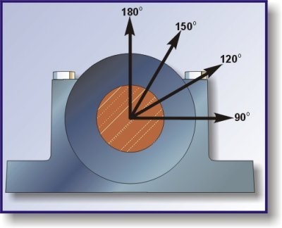
Influence of the direction of loading art the strength of plummet block housings.
Approximate values of the breaking load (P) for the housings, and the yield point (0) for the cap bolts are given in the following tables for different radial directions of loading. When the load acts at an angle of 55 deg. the cap bolts carry no load; Q is always greater than P when the load acts at an angle of 90 deg.
In the axial direction the breaking load is approximately 65 % of P180 deg.
Strength of SNA and SSNAD plummer block housing |
||||||||||||
Housing |
Breaking load for SNA housings * |
Yield point for the two cap bolts |
||||||||||
SNA housings |
SSNAD housings |
|||||||||||
Size |
P55 |
P90 |
P120 |
P150 |
P180 |
Q120 |
Q150 |
Q180 |
Q120 |
Q150 |
Q180 |
|
-- |
kN (1kN = 225lbf) |
kN (1kN = 225lbf) |
||||||||||
505 |
130 |
80 |
60 |
50 |
65 |
90 |
50 |
45 |
-- |
-- |
-- |
|
506-605 |
140 |
85 |
65 |
55 |
70 |
90 |
50 |
45 |
-- |
-- |
-- |
|
507-606 |
160 |
95 |
70 |
65 |
80 |
90 |
50 |
45 |
-- |
-- |
-- |
|
508-607 |
180 |
110 |
80 |
70 |
90 |
90 |
50 |
45 |
-- |
-- |
-- |
|
509 |
190 |
115 |
85 |
75 |
95 |
90 |
50 |
45 |
-- |
-- |
-- |
|
510-608 |
220 |
130 |
100 |
90 |
110 |
90 |
50 |
45 |
-- |
-- |
-- |
|
511-609 |
230 |
140 |
105 |
95 |
115 |
130 |
70 |
65 |
290 |
160 |
145 |
|
512-610 |
250 |
150 |
110 |
100 |
125 |
130 |
70 |
65 |
290 |
160 |
145 |
|
513-611 |
280 |
170 |
125 |
110 |
140 |
130 |
70 |
65 |
290 |
160 |
145 |
|
515-612 |
340 |
205 |
155 |
135 |
170 |
130 |
70 |
65 |
290 |
160 |
145 |
|
516-613 |
360 |
215 |
160 |
145 |
180 |
230 |
125 |
115 |
290 |
160 |
145 |
|
517 |
400 |
240 |
180 |
160 |
200 |
230 |
125 |
115 |
290 |
160 |
145 |
|
518-615 |
460 |
280 |
210 |
180 |
230 |
440 |
240 |
220 |
540 |
300 |
270 |
|
519-616 |
480 |
290 |
220 |
190 |
240 |
440 |
240 |
220 |
540 |
300 |
270 |
|
520-617 |
520 |
310 |
230 |
210 |
260 |
620 |
340 |
310 |
850 |
470 |
425 |
|
522-619 |
620 |
370 |
280 |
250 |
310 |
620 |
340 |
310 |
850 |
470 |
425 |
|
524-620 |
720 |
430 |
320 |
290 |
360 |
620 |
340 |
310 |
850 |
470 |
425 |
|
526 |
820 |
490 |
370 |
330 |
410 |
900 |
500 |
450 |
1220 |
670 |
610 |
|
528 |
960 |
570 |
430 |
390 |
480 |
900 |
500 |
450 |
1220 |
670 |
610 |
|
530 |
1100 |
660 |
490 |
440 |
550 |
900 |
500 |
450 |
1220 |
670 |
610 |
|
532 |
1130 |
780 |
580 |
520 |
650 |
900 |
500 |
450 |
1220 |
670 |
610 |
* SSNAD housings have approximately twice the strength
Strength of SN plummer block housing
Housing
Breaking load for the housings *
Yield point for the two cap bolts
Designation P55
P55
P90
P120
P150
P180
Q120
Q150
Q180
--
kN (1kN = 225lbf)
kN (1kN = 225lbf)
SN505
--
70
40
30
30
35
80
45
40
SN506
SN605
80
50
35
30
40
80
45
40
SN507
SN606
90
55
40
35
45
80
45
40
SN508
SN607
100
60
45
40
50
80
45
40
SN509
--
110
65
50
45
55
80
45
40
SN510
SN608
120
70
55
50
60
80
45
40
SN511
SN609
140
85
60
55
70
140
80
70
SN512
SN610
150
90
65
60
75
140
80
70
SN513
SN611
170
100
70
70
85
140
80
70
SN515
SN612
190
110
85
75
95
140
80
70
SN516
SN613
220
130
100
90
110
240
130
120
SN517
--
240
140
110
95
120
240
130
120
SN518
SN615
260
160
120
100
130
240
130
120
--
SN616
280
170
130
110
140
240
130
120
SN520
SN617
340
200
150
140
170
540
300
270
SN522
--
440
260
200
180
220
540
300
270
SN524
--
520
310
230
210
260
540
300
270
SN526
--
620
370
280
250
310
760
420
380
SN528
--
720
430
320
290
360
1000
550
500
SN530
--
860
520
390
340
430
1000
550
500
SN532
--
1100
660
490
440
550
1000
550
500
* Housing series SN2 and SN3 have the same strength as those of series SN5 and SN6, respectively.
Strength of SD plummer block housing
Housing
Breaking load for the housings
Yield point for the four cap bolts
Designation
P55
P90
P120
P150
P180
Q120
Q150
Q180
--
kN (1kN = 225lbf)
kN (1kN = 225lbf)
SD3134
2100
1000
760
680
850
1500
830
750
SD3136
2400
1150
850
760
950
1500
830
750
SD3138
2700
1300
1000
880
1100
2000
1100
1000
SD3140
3200
1600
1150
1050
1300
2000
1100
1000
SD3144
4000
1900
1400
1400
1600
2000
1100
1000
SD3148
4200
2000
1500
1500
1700
3200
1800
1600
SD3152
4700
2300
1700
1700
1900
3200
1800
1600
SD3156
5000
2400
1800
1800
2000
3200
1800
1600
SD3160
6000
2900
2200
2200
2400
3200
1800
1600
SD3164
7000
3400
2500
2500
2800
3200
1800
1600
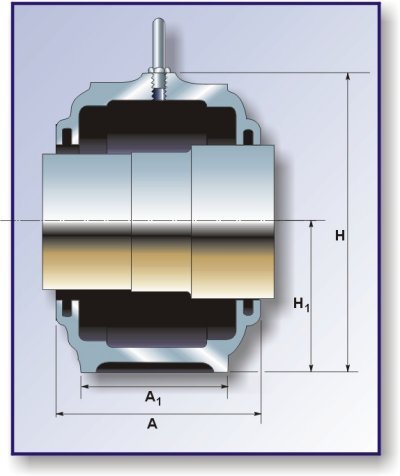
Shaft dia.
Housing Dimensions
Mass
Designation
da
db
A
A1
H
H1
H2
J
L
N
N1
G
mm
mm
kg
--
130
145
190
130
290
150
50
380
445
35
28
24
28.5
SN226
140
155
205
150
305
150
50
420
500
42
35
30
36.0
SN228
150
165
220
160
325
160
60
450
530
42
35
30
43.0
SN230
160
175
235
160
345
170
60
470
550
42
35
30
49.5
SN232
Shaft dia. |
Bearing Designation |
Basic Load Ratings |
Locating ring(s) Designation |
Mass per ring |
No. |
Felt Strip Designation |
No. |
Grease Initial fill |
|
da |
Dynamic |
Static |
|||||||
mm |
-- |
N |
-- |
kg |
-- |
-- |
-- |
kg |
|
130 |
22226 C/W33 |
480000 |
450000 |
FRB 13 |
0.28 |
2 |
FS510 |
2 |
1.40 |
23226 C/W33 |
600000 |
600000 |
FRB 10 |
0.21 |
1 |
||||
140 |
22228 C/W33 |
540000 |
500000 |
FRB 15 |
0.35 |
2 |
FS680 |
2 |
1.40 |
23228 C/W33 |
695000 |
710000 |
FRB 10 |
0.23 |
1 |
||||
150 |
22230 C/W33 |
640000 |
620000 |
FRB 16 |
0.42 |
2 |
FS680 |
2 |
1.80 |
23230 C/W33 |
815000 |
830000 |
FRB 10 |
0.25 |
1 |
||||
160 |
22232 C/W33 |
750000 |
735000 |
FRB 17 |
0.46 |
2 |
FS680 |
2 |
2.00 |
23232 C/W33 |
930000 |
950000 |
FRB 10 |
0.27 |
1 |
REF NO. |
d1 |
SPHERICAL ROLLER BRG. + ADAPTOR SLEEVE. |
A |
H1 |
H2 |
H |
L |
A1 |
J |
J1 |
J3 |
J4 |
J2 |
V |
d2 |
B |
|
SDX 31106 |
500 |
231 / 530 |
CAK/W33 + OH31106 |
484 |
500 |
980 |
1100 |
1140 |
450 |
980 |
320 |
70 |
54 |
35 |
80 |
870 |
190 |
SDX 3196 |
450 |
23196 |
CAK/W33 + OH3196 |
458 |
470 |
910 |
1030 |
1040 |
440 |
880 |
310 |
70 |
54 |
35 |
80 |
790 |
170 |
SDX 3192 |
430 |
23192 |
CAK/W33 + OH3192 |
450 |
470 |
890 |
1010 |
1040 |
440 |
880 |
310 |
70 |
54 |
35 |
80 |
760 |
165 |
SDX 3188 |
410 |
23188 |
CAK/W33 + OH3188 |
436 |
440 |
840 |
960 |
940 |
400 |
810 |
280 |
64 |
48 |
35 |
70 |
720 |
155 |
SDX 3184 |
400 |
23184 |
CAK/W33 + OH3184 |
434 |
440 |
840 |
955 |
940 |
400 |
810 |
280 |
64 |
48 |
35 |
70 |
700 |
150 |
SDX 3180 |
380 |
23180 |
CAK/W33 + OH3180 |
400 |
390 |
755 |
860 |
880 |
380 |
760 |
280 |
64 |
48 |
35 |
70 |
700 |
140 |
SDX 3176 |
360 |
23176 |
CAK/W33 + OH3176 |
385 |
390 |
742 |
850 |
880 |
380 |
760 |
280 |
64 |
48 |
35 |
65 |
620 |
130 |
SDX 3172 |
340 |
23172 |
CAK/W33 + OH3172 |
380 |
360 |
700 |
800 |
830 |
350 |
700 |
240 |
64 |
48 |
30 |
50 |
600 |
128 |
SDX 3168 |
320 |
23168 |
CAK/W33 + OH3168 |
380 |
360 |
690 |
790 |
830 |
350 |
700 |
240 |
64 |
48 |
30 |
50 |
600 |
110 |
A marked improvement compared with earlier plummet blocks is that different types of seal can be used. The standard seals supplied by SKF are V-ring and felt seals. They are delivered in special packages to-gether with the housings. Fitting is very simple.
V-ring seals
The V-ring, which is of synthetic rubber, has a thin sealing lip, which functions in an axial direction. The ring also acts as a flinger as it rotates with the shaft. This type of seal can be used with both grease and oil lubrication and is extremely effective under most operating conditions including high speeds.
The V-rings in SNA plummer blocks seal against sheet metal washers with a rust preventive coating and placed in the grooves of the housing. Each washer has a rubber lip bonded around its periphery and which bears against the housing. However, in plummer blocks SNA 205 to SNA 218 the V-rings seal directly against the housing; in this case the side faces of the housings are machined.
SNA plummer blocks with V-ring seals are given the suffix TA, for example SNA 505 TA.
Felt seals
The felt seal is a simple but adequate seal which can be used with grease lubrication and at peripheral speeds of up to some 4 m/s. Plummer blocks of series SNA 5 and SNA 6 are obtainable with split felt seals consisting of oiled felt incorporated in a light alloy ring in two pieces. These are pressed into the housing grooves after first inserting rubber strings, which serve both as an effective seal between the housing and the light alloy ring and also to prevent this from rotating. Plummer blocks SNA 205 to SNA 218 may also be supplied with felt seals but they comprise loose felt strips that are fitted directly in the grooves, i.e. they have no metal backing.
SNA plummer blocks with felt seals are given the suffix TO, for sample SNA 505 TO.
Supplementary sealing components
Protective collars
Where operating conditions are severe, the V-ring and felt seals of plummet blocks SNA 505 to SNA 518 and SNA 605 to SNA 615 may be supplemented by a light alloy collar, a standard component available from SKF. The collar protects the seals against damage and also im-proves the sealing effect. The bore diameter tolerance is H10.
The protective collars are designated TSNA (000) B, for example TSNA 505 B.
End covers
If the bearing is mounted at the end of a shaft, the bore at the outer side of the housing should be closed by means of a special cover. The end covers, which are supplied separately in packages, are designated ASNA followed by the number of the housing, for example ASNA 506-605. Plummer blocks of the series most frequently used, SNA 5 and SNA 6, are available with a seal set comprising one end. cover and one V-ring seal and are then given the suffix ATA, for example SNA 505 ATA.
Special seals for plummer blocks of type SNA
Essential manufacturing data
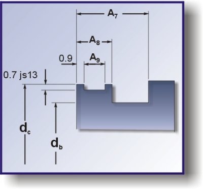
In TSP 6020, "Plummet blocks of type SNA", some types of special seal are shown on page 5, and the related application dimensions of the housings are given in the table section. This leaflet gives the dimensions required for the manufacture of the seals, which are easily made from tubular material.
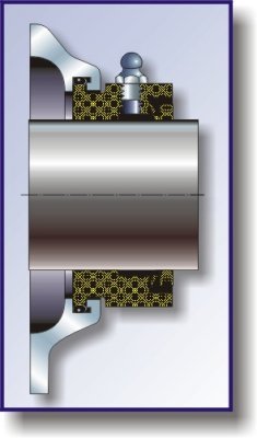
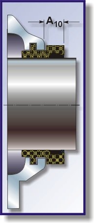
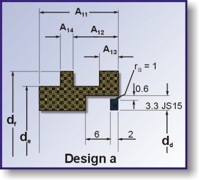
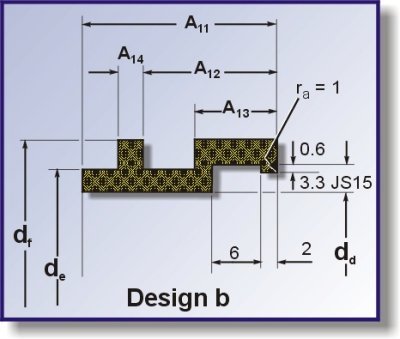
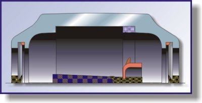
Illustrated on this page are two seals for extremely severe operating conditions, a labyrinth seal and a combined V-ring and gap seal equipped with a nipple for lubricating the V-ring. The table gives the dimensions necessary to ensure that the seals fit the housings; other dimensions may be varied. However, in view of the manufacturing tolerances, the bearing internal clearance and inevitable misalignment, sufficient radial clearance in the labyrinth must be ensured.
Housing |
Sealing collar dimensions |
O ring |
||||
db |
dc |
A7 |
A8 |
A9 |
65 5 IRH |
|
h11 |
h11 |
h13 |
h13 |
|
|
|
Designation |
mm |
mm |
||||
SNA 505 |
31,5 |
37 |
8,5 |
4,8 |
3 |
34,2 x 3 |
SNA 506-605 |
36,5 |
42 |
8,5 |
4,8 |
3 |
39,2 x 3 |
SNA 507-606 |
46,5 |
52 |
8,5 |
4,8 |
3 |
49,5 x 3 |
SNA 508-607 |
51,5 |
57 |
8,5 |
4,8 |
3 |
54,5 x 3 |
SNA 509 |
56,5 |
62 |
9,5 |
4,8 |
3 |
59,5 x 3 |
SNA 510-608 |
62 |
68 |
9,5 |
4,8 |
3 |
64,5 x 3 |
SNA 511-609 |
67 |
73 |
9,5 |
4,8 |
3 |
69,5 x 3 |
SNA 512-610 |
72 |
78 |
9,5 |
4,8 |
3 |
74,5 x 3 |
SNA 513-611 |
77 |
83 |
9,5 |
4,8 |
3 |
79,5 x 3 |
SNA 515-612 |
87 |
93 |
9,5 |
4,8 |
3 |
89,5 x 3 |
SNA 516-613 |
92,5 |
98,5 |
12 |
4,8 |
3 |
94,5 x 3 |
SNA 517 |
97,5 |
103,5 |
12 |
4,8 |
3 |
99,5 x 3 |
SNA 518-615 |
102,5 |
108,5 |
12 |
4,8 |
3 |
104,5 x 3 |
SNA 529-616 |
131 |
137 |
13 |
5,8 |
4 |
134 x 4 |
SNA 520-617 |
137,5 |
143,5 |
13 |
5,8 |
4 |
140 x 4 |
SNA 522-619 |
147,5 |
153,5 |
13 |
5,8 |
4 |
150 x 4 |
SNA 524-620 |
157,5 |
163,5 |
13 |
5,8 |
4 |
160 x 4 |
SNA 526 |
167,5 |
173,5 |
14,5 |
5,8 |
4 |
170 x 4 |
SNA 528 |
177,5 |
183,5 |
14,5 |
5,8 |
4 |
180 x 4 |
SNA 530 |
192,5 |
198,5 |
15 |
5,8 |
4 |
192 x 4 |
SNA 532 |
202,5 |
208,5 |
15 |
5,8 |
4 |
205 x 4 |
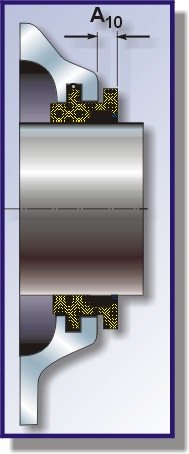
The labyrinth seal, type TS, shown on this page, is recommended in cases where SKF standard seals cannot be used for one reason or another, for instance if they do not match the diameter of the shaft. Depending on the radial space available for the collar, the (a) or (b) design should be chosen.
x 2 design a design b
Housing |
Sealing collar |
Rubber cord |
||||||||
Design |
Dimensions |
4mm dia. |
||||||||
dd |
de |
df |
A10 |
A11 |
A12 |
A13 |
A14 |
Length |
||
H9 |
h13 |
h13 |
|
h13 |
JS13 |
|
h13 |
|
||
Designation |
-- |
mm |
mm |
|||||||
SNA 505 |
a |
Max.21 |
30,5 |
37,5 |
6,5 |
18 |
10 |
4,5 |
3 |
75 |
b |
21-27 |
30,5 |
37,5 |
12 |
23 |
15,5 |
10 |
3 |
95 |
|
SNA 506-605 |
a |
Max.26 |
35,5 |
42,5 |
6,5 |
18 |
10 |
4,5 |
3 |
95 |
b |
26-32 |
35,5 |
42,5 |
12 |
23 |
15,5 |
10 |
3 |
115 |
|
SNA 507-606 |
a |
Max.36 |
45,5 |
52,5 |
6,5 |
18 |
10 |
4,5 |
3 |
125 |
b |
36-41,5 |
45,5 |
52,5 |
12 |
23 |
15,5 |
10 |
3 |
140 |
|
SNA 508-607 |
a |
Max.41 |
50,5 |
57,5 |
6,5 |
18 |
11 |
4,5 |
3 |
140 |
b |
41-46,5 |
50,5 |
57,5 |
12 |
23 |
16,5 |
10 |
3 |
155 |
|
SNA 509 |
a |
Max.46 |
55,5 |
62,5 |
6,5 |
19 |
11 |
4,5 |
3 |
155 |
b |
46-51.5 |
55,5 |
62,5 |
12 |
24 |
16,5 |
10 |
3 |
175 |
|
SNA 510-608 |
a |
Max.51 |
61 |
68,5 |
6,5 |
19 |
11 |
4,5 |
3 |
175 |
b |
51-57 |
61 |
68,5 |
12 |
24 |
16,5 |
10 |
3 |
195 |
|
SNA 511-609 |
a |
Max.56 |
66 |
73,5 |
6,5 |
19 |
11 |
4,5 |
3 |
185 |
b |
56-62 |
66 |
73,5 |
12 |
24 |
16,5 |
10 |
3 |
205 |
|
SNA 512-610 |
a |
Max.61 |
71 |
78,5 |
6,5 |
19 |
11 |
4,5 |
3 |
205 |
b |
61-67 |
71 |
78,5 |
12 |
24 |
16,5 |
10 |
3 |
225 |
|
SNA 513-611 |
a |
Max.66 |
76 |
83,5 |
6,5 |
19 |
11 |
4,5 |
3 |
225 |
b |
66-72 |
76 |
83,5 |
12 |
24 |
16,5 |
10 |
3 |
245 |
|
SNA 515-612 |
a |
Max.75 |
85,5 |
93 |
6,5 |
19 |
11 |
4,5 |
3 |
245 |
b |
75-81.5 |
85,5 |
93 |
12 |
24 |
16,5 |
10 |
3 |
270 |
|
SNA 516-613 |
a |
Max.80 |
91 |
98,5 |
7,5 |
22 |
14 |
5 |
3 |
260 |
b |
80-87 |
91 |
98,5 |
12,5 |
27 |
19 |
10 |
3 |
290 |
|
SNA 517 |
a |
Max.85 |
96 |
103,5 |
7,5 |
22 |
14 |
5 |
3 |
280 |
b |
85-92 |
96 |
103,5 |
12,5 |
27 |
19 |
10 |
3 |
305 |
|
SNA 518-615 |
a |
Max.90 |
101 |
108,5 |
7,5 |
23 |
14 |
5 |
3 |
305 |
b |
90-97 |
101 |
108,5 |
12,5 |
28 |
19 |
10 |
3 |
320 |
|
SNA 529-616 |
a |
Max.118 |
129,5 |
138,5 |
7,5 |
24 |
14 |
5 |
4 |
375 |
SNA 520-617 |
a |
Max.125 |
136 |
145 |
7,5 |
24 |
14 |
5 |
4 |
405 |
SNA 522-619 |
a |
Max.135 |
146 |
155 |
7,5 |
24 |
14 |
5 |
4 |
440 |
SNA 524-620 |
a |
Max.145 |
156 |
165 |
7,5 |
24 |
14 |
5 |
4 |
460 |
SNA 526 |
a |
Max.155 |
166 |
175 |
8 |
26 |
16 |
5,5 |
4 |
500 |
SNA 528 |
a |
Max.165 |
176 |
185 |
8 |
26 |
16 |
5,5 |
4 |
530 |
SNA 530 |
a |
Max.180 |
191 |
200 |
8 |
27 |
16,5 |
5,5 |
4 |
590 |
SNA 532 |
a |
Max.190 |
201 |
210 |
8 |
27 |
16,5 |
5,5 |
4 |
620 |
Locating rings
The bearing seating in the housings is sufficiently wide to allow axial freedom for any bearing. A bearing which is to locate the shaft should therefore be fixed in position by means of one or more locating rings. If this bearing is mounted on an adapter sleeve, the locating rings should be placed as follows:
1 ring - on the same side as the sleeve nut
2 rings - one on each side of the bearing
3 rings - two on the same side as the sleeve nut
4 rings - two on each side of the bearing
COLLAR |
d1 |
D |
W |
A |
TSNA 509 B |
40 |
92 |
30 |
20 |
TSNA 511 B |
50 |
111 |
30 |
22 |
TSNA 513 B |
60 |
115 |
30 |
20 |
TSNA 515 B |
65 |
122 |
22 |
16 |
TSNA 516 B |
70 |
130 |
30 |
20 |
TSNA 517 B |
75 |
135 |
30 |
22 |
TSNA 518 B |
80 |
145 |
34 |
26 |
TSNA 520 B |
90 |
185 |
45 |
30 |
TSNA 522 B |
100 |
190 |
27 |
20 |
TSNA 524 B |
110 |
210 |
40 |
30 |
TSNA 526 B |
115 |
220 |
40 |
30 |
TSNA 528 B |
125 |
235 |
40 |
30 |
TSNA 532 B |
140 |
250 |
40 |
30 |
BRG. SHAFT DIA. |
V-RING SEAL & WASHERS |
FELT SEAL |
V-RING COVER PLATE |
POLY-URETHANE COLLAR |
LOCATING RING |
LABYRINTH SEAL O-RING |
END COVER |
50 |
TA |
TC |
ATA |
TSNA511 |
FRB9,5/100P |
TS11 |
ASNA511 |
75 |
TA |
TC |
ATA |
TSNA517 |
FRB12,5/150P |
TS17 |
ASNA517 |
90 |
TA |
TC |
ATA |
TSNA520 |
FRB12/180P |
TS20 |
ASNA520 |
100 |
TA |
TC |
ATA |
TSNA522 |
FRB13,5/200P |
TS22 |
ASNA522 |
110 |
TA |
TC |
ATA |
TSNA524 |
FRB14/215P |
TS24 |
ASNA524 |
125 |
TA |
TC |
ATA |
TSNA528 |
FRB15/250P |
TS28 |
ASNA528 |
140 |
TA |
TC |
ATA |
TSNA532 |
FRB17/290P |
TS32 |
ASNA532 |
160 |
|
|
|
|
FRB10/300 |
TS36 |
716150/36 |
180 |
|
|
|
|
FRB10/340 |
TS40 |
716150/40 |
200 |
|
|
|
|
FRB10/370 |
TS44 |
716150/44 |
220 |
|
|
|
|
FRB10/400 |
TS48 |
716150/48 |
240 |
|
|
|
|
FRB10/440 |
TS52 |
716150/52 |
260 |
|
|
|
|
FRB10/460 |
TS56 |
716150/56 |
280 |
|
|
|
|
FRB10/500 |
TS60 |
716150/60 |
300 |
|
|
|
|
FRB10/540 |
TS64 |
716150/64 |
320 |
|
|
|
|
/580 |
TS68 |
716150/68 |
340 |
|
|
|
|
/600 |
TS72 |
716150/72 |
360 |
|
|
|
|
/620 |
TS76 |
716150/76 |
380 |
|
|
|
|
/650 |
TS80 |
716150/80 |
400 |
|
|
|
|
/700 |
TS84 |
716150/84 |
410 |
|
|
|
|
/720 |
TS88 |
716150/88 |
430 |
|
|
|
|
/760 |
TS92 |
716150/92 |
450 |
|
|
|
|
/790 |
TS96 |
716150/96 |
500 |
|
|
|
|
/870 |
TS106 |
716150/106 |
- Suffix TA to housing e.g. SNA 520 TA, indicates supplied with two V-ring seals and washers.
- Suffix TC to housing e.g. SNA 520 TC, indicates supplied with two felt seals and light alloy rings.
- Suffix ATA e.g. SNA 520 ATA, indicates supplied with one V-ring seal and washer and one end cover.
- For polyurethane protective collars see standard No. CM/0900/PB1B. When calling up these parts the material must be stated since SKF also supply light alloy collars with corresponding part nos.
- Locating ring designation indicates width and o/dia e.g. 10/370 = 10 wide x 370 o/dia.
- For details of labyrinth seals and 0-rings see standard No. CM/0900/PB1A.
- For Teconite seals see drawing No. 2156428.
References
SKF - General Catalogue 3000 IIE/GB666 11 - July 1978.
SKF - SNA Plummer Blocks Ref. No. TSP 6020.
SKF - Special Seals for SNA Plummer Blocks Ref. No. TSP 6021
SKF - Drawing No. 2156428.