Soleplates
SKF

Notes:
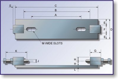
To be supplied with 2 hex set screws J dia. x k long and 2 plain nuts.
6mm full weld all round jacking blocks
Soleplates to be fully welded to supporting steelwork
All dimensions in millimetres
Shop weld to steelwork
Slotted holes in steelwork
BEL REF. |
DIMENSIONS |
MASS kg. |
|||||||||||||
A |
B |
C |
D |
E |
F |
G |
H |
J |
K |
L |
M |
N |
P |
||
001 |
130 |
235 |
305 |
50 |
10 |
30 |
40 |
15 |
M12 |
115 |
8 |
15 |
M12 |
40 |
2,5 |
002 |
150 |
255 |
325 |
55 |
12,5 |
30 |
40 |
15 |
M12 |
115 |
8 |
15 |
M12 |
40 |
2,7 |
003 |
170 |
275 |
345 |
65 |
17,5 |
30 |
40 |
15 |
M12 |
115 |
8 |
15 |
M12 |
40 |
3,5 |
004 |
210 |
330 |
400 |
75 |
17,5 |
40 |
40 |
20 |
M16 |
115 |
10 |
19 |
M16 |
45 |
5,0 |
005 |
230 |
355 |
425 |
85 |
22,5 |
40 |
40 |
20 |
M16 |
115 |
10 |
19 |
M16 |
45 |
5,8 |
006 |
260 |
395 |
465 |
100 |
30 |
40 |
40 |
20 |
M16 |
115 |
10 |
24 |
M20 |
45 |
7,1 |
007 |
290 |
420 |
510 |
110 |
30 |
50 |
50 |
25 |
M16 |
125 |
10 |
24 |
M20 |
45 |
9,2 |
008 |
320 |
460 |
550 |
120 |
35 |
50 |
50 |
25 |
M20 |
125 |
10 |
28 |
M26 |
50 |
10,8 |
009 |
350 |
490 |
580 |
130 |
40 |
50 |
50 |
25 |
M20 |
125 |
12 |
28 |
M26 |
50 |
11,9 |
010 |
380 |
525 |
615 |
140 |
45 |
50 |
50 |
25 |
M20 |
140 |
12 |
28 |
M26 |
50 |
13,2 |
011 |
420 |
590 |
680 |
160 |
55 |
50 |
50 |
25 |
M20 |
140 |
12 |
35 |
M30 |
60 |
15,9 |
012 |
450 |
620 |
710 |
170 |
60 |
50 |
50 |
25 |
M20 |
140 |
12 |
35 |
M30 |
60 |
17,4 |
013 |
470 |
640 |
730 |
170 |
60 |
50 |
50 |
25 |
M20 |
140 |
12 |
35 |
M30 |
60 |
17,9 |
SOLEPLATE |
SKF. PLUMMER BLOCK SERIES |
|||||||
BEL. REF. No. |
SNA.6 |
SN.6 |
SNA.5 |
SN.5 |
SNA.3 |
SN.3 |
SNA.2 |
SN.2 |
001 |
|
|
505 |
505 |
|
|
205 |
205 |
002 |
605 |
605 |
506 |
506 |
|
305 |
206 |
206 |
002 |
606 |
606 |
507 |
507 |
|
306 |
207 |
207 |
003 |
607 |
607 |
508 |
508 |
|
307 |
208 |
208 |
003 |
608 |
608 |
509 |
509 |
308 |
308 |
209 |
209 |
003 |
|
|
510 |
510 |
|
|
210 |
210 |
004 |
609 |
609 |
511 |
511 |
309 |
309 |
211 |
211 |
004 |
610 |
610 |
512 |
512 |
310 |
310 |
212 |
212 |
005 |
611 |
611 |
513 |
513 |
311 |
311 |
213 |
213 |
005 |
|
|
|
|
|
|
|
214 |
005 |
612 |
612 |
515 |
515 |
312 |
312 |
215 |
215 |
006 |
613 |
613 |
516 |
516 |
313 |
313 |
216 |
216 |
006 |
|
|
517 |
517 |
314 |
314 |
217 |
217 |
007 |
615 |
615 |
518 |
518 |
315 |
315 |
218 |
218 |
007 |
616 |
616 |
519 |
|
316 |
316 |
|
|
008 |
617 |
617 |
520 |
520 |
317 |
317 |
220 |
220 |
009 |
619 |
|
522 |
522 |
|
|
222 |
222 |
009 |
620 |
|
524 |
524 |
|
|
224 |
224 |
010 |
|
|
526 |
526 |
|
|
226 |
226 |
011 |
|
|
528 |
528 |
|
|
228 |
228 |
012 |
|
|
530 |
530 |
|
|
230 |
230 |
013 |
|
|
532 |
532 |
|
|
232 |
232 |
For details of plummer blocks see CM/0900/PB1
For details of soleplates see CM/0900/PB2 sheet 1

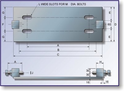
Notes:
To be supplied with 2 hex set screws J dia. x k long and 2 plain nuts.
6mm full weld all round jacking blocks
Soleplates to be tack welded to supporting steelwork
All dimensions in millimetres
BEL REF. |
SD. BRG. HSG |
SHAFT DIA. |
DIMENSIONS |
MASS kg. |
||||||||||||
A |
B |
C |
D |
E |
F |
G |
H |
J |
K |
L |
M |
N |
||||
101 |
3134 |
150 |
430 |
600 |
680 |
200 |
70 |
100 |
50 |
50 |
M24 |
150 |
28 |
M24 |
60 |
20,6 |
102 |
3136 |
160 |
450 |
620 |
700 |
200 |
70 |
110 |
45 |
50 |
M24 |
150 |
28 |
M24 |
60 |
21,1 |
103 |
3138 |
170 |
480 |
650 |
730 |
230 |
85 |
120 |
55 |
50 |
M24 |
150 |
28 |
M24 |
60 |
24,6 |
104 |
3140 |
180 |
510 |
700 |
780 |
250 |
95 |
130 |
60 |
50 |
M24 |
150 |
35 |
M30 |
60 |
27,8 |
105 |
3144 |
200 |
540 |
730 |
810 |
250 |
95 |
140 |
55 |
50 |
M24 |
150 |
35 |
M30 |
60 |
28,8 |
106 |
3148 |
220 |
600 |
790 |
920 |
280 |
110 |
150 |
65 |
75 |
M30 |
180 |
35 |
M30 |
60 |
37,2 |
107 |
3152 |
240 |
650 |
870 |
1000 |
300 |
120 |
160 |
70 |
75 |
M30 |
180 |
42 |
M36 |
70 |
42,3 |
108 |
3156 |
260 |
670 |
890 |
1020 |
300 |
120 |
160 |
70 |
75 |
M30 |
180 |
42 |
M36 |
70 |
43,0 |
109 |
3160 |
280 |
710 |
930 |
1060 |
330 |
135 |
190 |
70 |
75 |
M30 |
180 |
42 |
M36 |
70 |
48,6 |
110 |
3164 |
300 |
750 |
980 |
1110 |
350 |
145 |
200 |
75 |
75 |
M30 |
180 |
42 |
M36 |
70 |
53,4 |

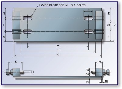
Notes:
To be supplied with 4 hex set screws J dia. x k long and 4 plain nuts.
6mm full weld all round jacking blocks
Soleplates to be tack welded to supporting steelwork
All dimensions in millimetres
BEL REF. |
SD. BRG. HSG |
SHAFT DIA. |
DIMENSIONS |
MASS kg. |
|||||||||||
A |
B |
C |
D |
F |
G |
H |
J |
K |
L |
M |
N |
||||
101 |
3134 |
150 |
430 |
600 |
680 |
200 |
100 |
50 |
50 |
M24 |
150 |
28 |
M24 |
60 |
20,6 |
102 |
3136 |
160 |
450 |
620 |
700 |
200 |
110 |
45 |
50 |
M24 |
150 |
28 |
M24 |
60 |
21,1 |
103 |
3138 |
170 |
480 |
650 |
730 |
230 |
120 |
55 |
50 |
M24 |
150 |
28 |
M24 |
60 |
24,6 |
104 |
3140 |
180 |
510 |
700 |
780 |
250 |
130 |
60 |
50 |
M24 |
150 |
35 |
M30 |
60 |
27,8 |
105 |
3144 |
200 |
540 |
730 |
810 |
250 |
140 |
55 |
50 |
M24 |
150 |
35 |
M30 |
60 |
28,8 |
106 |
3148 |
220 |
600 |
790 |
920 |
280 |
150 |
65 |
75 |
M30 |
180 |
35 |
M30 |
60 |
37,2 |
107 |
3152 |
240 |
650 |
870 |
1000 |
300 |
160 |
70 |
75 |
M30 |
180 |
42 |
M36 |
70 |
42,3 |
108 |
3156 |
260 |
670 |
890 |
1020 |
300 |
160 |
70 |
75 |
M30 |
180 |
42 |
M36 |
70 |
43,0 |
109 |
3160 |
280 |
710 |
930 |
1060 |
330 |
190 |
70 |
75 |
M30 |
180 |
42 |
M36 |
70 |
48,6 |
110 |
3164 |
300 |
750 |
980 |
1110 |
350 |
200 |
75 |
75 |
M30 |
180 |
42 |
M36 |
70 |
53,4 |

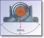
All plummer blocks must be mounted such that the direction of the force imposed by the shaft shall fall within the limits of the angle A.
I.e. The angle subtended at the centre of the shaft by the intersection of the centre lines of the holding down boltholes and the underside of the plummer block base.
Ideally, the direction of the force should be vertically downwards through the centre of the shaft when related to the sketch above.
Plummer block mountings must be arranged accordingly.
