Primary scrapers comprise a scraper blade (1) mounted onto a supporting shaft / beam (2). The shaft / beam is 'spring loaded' by means of either rubber bushes or an adjustable torque arm (3). The scraper support is then bolted onto the conveyors' head chute support steelwork (4) at either side of the chute.
b) Secondary belt scrapers
These scrapers are installed within the head chute and are designed to remove any residual material which is not removed by the primary scraper, before the belt commences its return to the tail-end of the conveyor.
Examples of secondary belt scrapers include the following :-
- Single blade scrapers
When used on contact with the belt on a crowned pulley, the blade wears to conform to the shape of the belt and pulley. -
Dual blade scrapers
The adjacent picture is an example of a dual bladed scraper. -
Articulated blade scrapers
This scraper design consists of a series of short blades(1) pivoted on arms (2) which are spring-loaded to maintain contact with the belt surface.
-
Rotary belt cleaners
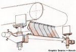
The blade usually is made so that it can be adjusted from time to time for the most effective cleaning action.
As with primary scrapers, the removable blade(s) of the scraper (1) are bolted onto a support bar (2) which spans the width of the conveyor chute work and protrudes outside of the chute on either side.
The support bar is also a torsion bar as it applies the necessary force onto the scraper blades to ensure that they remain in contact with the belt at all times. The support bar is then connected to the scraper support mechanism (3) which is bolted to the chute via a support bracket (4). The adjustment mechanism (5) is usually mounted outside the chute for maintenance accessibility.
Material buildup on the scraper blades is prevented by the inclusion of low-friction liners (6) attached to each blade.
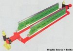
The two blades (1) are pivoted on bushes (2) at either end of the support (3). The pressure which is applied to the belt is adjusted on the scraper's attachment brackets (4) on either side of the scraper.
The feature of the pivot enables both rows of blades to maintain effective contact with the belt and the twin row of blades improves cleaning.
The blades are arranged in a staggered, over-lapping pattern so that the entire width of the belt is cleaned efficiently.
The independent blades offer the advantages of self-adjusting to the belt surface, compensation for wearing of the blades and any deflection or vibration during use causes buildup on the scraper to being dislodged.
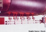
This type of belt cleaner must be inspected relatively frequently, adjusted and cleaned so that the blades are free to pivot and to contact the belt properly.
Rotary cleaners consist of power driven shafts (1) or tubes to which brush bristles (2) or blades are attached. The shaft is can be driven by an independent drive unit (3) or by the head pulley shaft via a chain or pulley drive.
These brushes or blades are made wider than the normal belt width to ensure adequate cleaning across the belt.
A number of variations to brush-type cleaners and rotary blade cleaners are available however the two categories are outlined below.

The brush bristles are made of nylon or bassine and in the case of blades, are made of rubber and are designed to develop have a 'flicking' action when in service.
Rotary brush cleaners are not commonly used in bulk materials handling and they are best suited to lighter duties and where the spillage is a dusty or dry granular material.
Material build-up in the brush can be a problem when these cleaners are used in wet and sticky applications. The brushes are usually arranged in a helical pattern to expel material and prevent clogging.
Brush cleaners can be either high- or low speed rotation. Low-speed rotary brush cleaners are designed to operate at peripheral speeds of 2.05 to 3.08 m/s, and are most effective on dry granular materials. This design gives a longer life because the lower speed causes less wear on the bristles.
High-speed rotary brushes are designed to operate at peripheral speeds of 5.13 to 7.7 m/s and are more effective on damp granular materials as the higher rotary speed produces centrifugal dislodgement of material from the bristles.
The rotary-blade type belt cleaners use rubber blades arranged parallel to the shaft rather than bristles arranged radially around the shaft. The blades are forced against the return belt and the scraping action removes material and 'flings' it into the chute.
As with the brush scrapers, blade scrapers are available in two speeds. Low-speed rotary cleaners have a peripheral speed of approximately 5 m/s and are used on either dry or damp materials.
High-speed rotary blade cleaners have a peripheral speed of approximately 7 m/s and is best suited for applications where the material is wet and sticky.
The direction of rotation of both the rotary brush and rotary blade cleaners is always opposite to the direction of the conveyor belt travel.
c) Belt washing systems
As with contact scrapers, there are a number of variations to the design of belt washing systems and it is often true that belt washing stations are optimised only through use and experience on site.
Belt washing is normally only considered when the nature of the material transported (and hence residual material) is extremely 'sticky' and / or extremely abrasive on contact scrapers to the extent that it is viable to turn to a washing system.
In such cases, belt washing is a tried and tested alternative belt cleaning technology.
There are three distinct disadvantages which belt washing systems have relative to contact scrapers namely;
- Clean water must be routed to the washing facility from a reliable source. Clean water is essential to prevent nozzle blockage by scaling or deposition, which would reduce the effectiveness of the washing system. Also, the water pressure should remain within design limits throughout operation, to ensure that the nozzles provide the necessary spray pattern and volume of water.
- The water supply must be interlocked with the conveyor operation and hence isolation valves with the associated cabling, interlocking via PLC's, etc. must be catered for and maintained to prevent water waste or water deprivation.
- Having cleaned the residual material off of the belt, the resulting slurry must be dealt with. The volumes of slurry can be high and the settlement period for many particulates is long, meaning that settlement ponds may be ineffective in curbing pollution. As a result, the slurry handling system can be more complicated and costly than the washing system itself !
A typical washing plant comprises the following (refer to sketch) :-
A water supply pipeline with isolation valve (1) connected to a water source and PLC for interlocking. The water supply is connected to the spray bar (2) which incorporates removable spray nozzles (3).

