| Process Automation Technical Data |
|
APPLICATION NOTES
Cyclone Blockage Detection System
for Pre-heater type Cement KilnsThe Problem
The blockages occuring in the Cyclone and/or Cyclone under flow occur as follows:-
Under normal conditions the cyclone under-flow pipe is not full of material. Due to a change in the process conditions the Cyclone under-flow pipe is no longer able to transport all the material being delivered to it. This results in the pipe filling with material.
If left unattended this will inevitably result in the material backing up into the cyclone causing a severe blockage which will result in subsequent plant downtime and significant production losses.

The Partial Solution
By installing a non-intrusive, gamma type, Cyclone under-flow blockage detector, it is possible to detect whenever this pipe fills up. This gauge provides a relay output which may be used to alarm/trip the kiln so as to allow appropriate action to be taken to clear the blockage.
The Complete Solution
The partial solution does not provide:-
Early warning of an impending blockage.
Indication of the full extent of the blockage which has occurred.
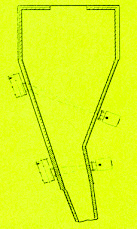
By making use of a non-intrusive Cyclone Blockage Detection System, it is possible to see the mass (thickness) of material in the Cyclone flowing down the Cyclone walls. The system provides a continuous analogue (4-20 mA) output proportional to this mass.
It has been found that under normal operational conditions the mass of material in the cyclone will be within certain defined limits. By placing this output either on a continuous strip chart recorder or panel meter (PVI), it is possible to monitor this condition. Should the mass change beyond the normal operating values, an alarm may be generated for appropriate action by the operator. This effectively provides an early warning of an impending choke.
Should the early warning from the Blocked Cyclone Detector be ignored, conditions may result in the Cyclone under-flow becoming filled, which (when so equipped) will result in a further alarm being generated, from the Cyclone Under-flow Blockage detector. After stopping the kiln, the Cyclone under-flow pipe may be opened and the blockage cleared.
Unfortunately this is not always the end of the story. Due to the inertia of the process, the material to the cyclone under-flow is not immediately interrupted by the stopping of the kiln. In-flight material continues to be delivered to the already full cyclone under-flow pipe which may result in this additional material backing up into the cyclone itself.
By opening and clearing the cyclone under-flow pipe, nothing may have been done to remove any material deposited/choking the cyclone.
Should the kiln now be restarted, under the impression that the choke has been cleared, it will inevitably result in the choke situation being considerably aggravated by the addition of further material into the already blocked cyclone.
The situation rapidly deteriorates into a major production disruption, not to mention the dangers associated with the difficulty of removing the now large volumes of very hot process material.
In addition to the early warning provided by the Blocked Cyclone Detection System, it will also provide an indication of any (choked) material that may exist in the bottom of the cyclone - after the clearing of the under-flow pipe blockage. This will allow the proper clearing of the choke from the cyclone prior to attempting a restart of the kiln.
About the Sensors
The features of the sensor set are:-
The Source Holder Assembly
The source holder is fabricated from thr mild steel (optionally others) to exceed the requirements of the department of National Health - Directorate: Health Technology. The isotope used is Caesium137 which provides a proper balance between measurement precision, longevity and cost.
The Detector Assembly
The detector housing is fabricated from mild steel (optionally others) and bolts to the pipe clamp. An optional safety shield is available to significantly reduce through radiation.
Due to the physical layout of the windows of the existing point detection system, a high sensitivity Scintillation detector is required.
Due to the nature of the measurement, high temperatures may be encountered. The Scintillation Detector system is rated to 50 degrees Celsius maximum.
For operation in higher ambient temperatures water cooling is required. When required, this Water Cooled option provides for a stainless steel detector housing with the necessary cooling jacket.
A high temperature/zero flow switch may be incorporated into the detector to forewarn of possible damage to the detector in the event of failure of the cooling system.
