Beginners Guide
STANDARD NO. CM/0900/LA1
RINGFEDER LOCKING ASSEMBLIESINDEX
Index and general notes
Basic dimensions
Mechanical properties
Machining tolerances
1. GENERAL NOTES
RINGFEDER locking assemblies are suitable for securing all types of bosses and hubs to shafts and axles.
No keyways or splines are required. Thus notch effect is eliminated and a high polar section modulus is available.
Assemblies require no stops. They can therefore be located and positively locked at any position on the shaft. When locking screws are tightened, the contact surfaces are pressed firmly together to prevent the ingress of dirt and moisture.
True running is assured since the frictional lock connection guarantees no play between mating surfaces. Assemblies can bridge relatively large clearances without significant torque losses. See also notes on sheet 5.
The table of mechanical properties given on sheet 4 is applicable to static, dynamic or impact loading but these figures must not be exceeded. If overloading takes place assemblies will slip, thus safeguarding equipment against damage. However, they must not be used as slipping clutches.
Assemblies may be used in series when the transmissible torques and axial loads are approximately additive.
Reference: RINGFEDER Locking Assemblies S79E. Sept.1978.
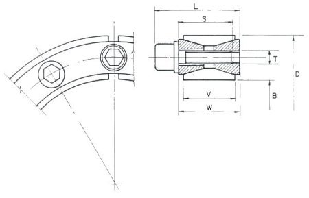
S.A. Agents: SURTEES AND SONS (Pty) LTD., Heriotdale.2. BASIC DIMENSIONS

For Mechanical Properties see: 3 Mechanical properties
For Machining Tolerances see: 4 Machining tolerances
BASIC DIMENSIONS |
LOCKING SCREW |
MASS kg. |
||||||
B |
D |
W |
V |
L |
T |
S |
No. |
|
20 |
47 |
20 |
17 |
27,5 |
M6 |
18 |
8 |
0,24 |
22 |
47 |
20 |
17 |
27,5 |
M6 |
18 |
8 |
0,23 |
24 |
50 |
20 |
17 |
27,5 |
M6 |
18 |
9 |
0,26 |
25 |
50 |
20 |
17 |
27,5 |
M6 |
18 |
9 |
0,25 |
28 |
55 |
20 |
17 |
27,5 |
M6 |
18 |
10 |
0,3 |
30 |
55 |
20 |
17 |
27,5 |
M6 |
18 |
10 |
0,29 |
35 |
60 |
20 |
17 |
27,5 |
M6 |
18 |
12 |
0,32 |
40 |
65 |
20 |
17 |
27,5 |
M6 |
18 |
14 |
0,34 |
45 |
75 |
24 |
20 |
33,5 |
M8 |
22 |
12 |
0,57 |
50 |
80 |
24 |
20 |
33,5 |
M8 |
22 |
12 |
0,6 |
55 |
85 |
24 |
20 |
33,5 |
M8 |
22 |
14 |
0,63 |
60 |
90 |
24 |
20 |
33,5 |
M8 |
22 |
14 |
0,69 |
65 |
95 |
24 |
20 |
33,5 |
M8 |
22 |
16 |
0,73 |
70 |
110 |
28 |
24 |
39,5 |
M10 |
25 |
14 |
1,26 |
75 |
115 |
28 |
24 |
39,5 |
M10 |
25 |
14 |
1,33 |
80 |
120 |
28 |
24 |
39,5 |
M10 |
25 |
14 |
1,4 |
85 |
125 |
28 |
24 |
39,5 |
M10 |
25 |
16 |
1,49 |
90 |
130 |
28 |
24 |
39,5 |
M10 |
25 |
16 |
1,53 |
95 |
135 |
28 |
24 |
39,5 |
M10 |
25 |
18 |
1,62 |
100 |
145 |
33 |
26 |
47,0 |
M12 |
30 |
14 |
2,01 |
110 |
155 |
33 |
26 |
47,0 |
M12 |
30 |
14 |
2,15 |
120 |
165 |
33 |
26 |
47,0 |
M12 |
30 |
16 |
2,35 |
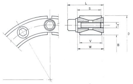
For Mechanical Properties see: 3 Mechanical properties
For Machining Tolerances see: 4 Machining tolerances
BASIC DIMENSIONS |
LOCKING SCREW |
MASS kg. |
||||||
B |
D |
W |
V |
L |
T |
S |
No. |
|
130 |
180 |
38 |
34 |
52 |
M12 |
35 |
20 |
3,51 |
140 |
190 |
38 |
34 |
52 |
M12 |
35 |
22 |
3,85 |
150 |
200 |
38 |
34 |
52 |
M12 |
35 |
24 |
4,07 |
160 |
210 |
38 |
34 |
52 |
M12 |
35 |
26 |
4,3 |
170 |
225 |
44 |
38 |
60 |
M14 |
40 |
22 |
5,78 |
180 |
235 |
44 |
38 |
60 |
M14 |
40 |
24 |
6,05 |
290 |
250 |
52 |
46 |
68 |
M14 |
45 |
28 |
8,25 |
200 |
260 |
52 |
46 |
68 |
M14 |
45 |
30 |
8,65 |
220 |
285 |
56 |
50 |
74 |
M16 |
50 |
26 |
11,22 |
240 |
305 |
56 |
50 |
74 |
M16 |
50 |
30 |
12,2 |
260 |
325 |
56 |
50 |
74 |
M16 |
50 |
34 |
13,2 |
280 |
355 |
66 |
60 |
86,5 |
M18 |
60 |
32 |
19,2 |
300 |
375 |
66 |
60 |
86,5 |
M18 |
60 |
36 |
20,5 |
320 |
405 |
78 |
72 |
100,5 |
M20 |
70 |
36 |
29,6 |
340 |
425 |
78 |
72 |
100,5 |
M20 |
70 |
36 |
31,1 |
360 |
455 |
90 |
84 |
116 |
M22 |
80 |
36 |
42,2 |
380 |
475 |
90 |
84 |
116 |
M22 |
80 |
36 |
44 |
400 |
495 |
90 |
84 |
116 |
M22 |
80 |
36 |
46 |
420 |
515 |
90 |
84 |
116 |
M22 |
80 |
40 |
50 |
440 |
545 |
102 |
96 |
130 |
M24 |
90 |
40 |
64,6 |
460 |
565 |
102 |
96 |
130 |
M24 |
90 |
40 |
67,4 |
480 |
585 |
102 |
96 |
130 |
M24 |
90 |
42 |
71 |
500 |
605 |
102 |
96 |
130 |
M24 |
90 |
44 |
72,6 |
3. MECHANICAL PROPERTIEST = TRANSMISSIBLE TORQUE
F = AXIAL FORCE ABSORBED
Ps = PRESSURE BETWEEN LOCKING ASSEMBLY AND SHAFT
PH = PRESSURE BETWEEN LOCKING ASSEMBLY AND HUB
M = TORQUE PER LOCKING SCREW (APPLIED BY TORQUE WRENCH)
B |
T |
F |
Ps |
PH |
M |
B |
T |
F |
Ps |
PH |
M |
20 |
0,27 |
27 |
210 |
90 |
14 |
140 |
20 |
298 |
165 |
125 |
125 |
22 |
0,30 |
27 |
195 |
90 |
14 |
150 |
24 |
324 |
170 |
125 |
125 |
24 |
0,36 |
30 |
195 |
90 |
14 |
160 |
28 |
350 |
170 |
130 |
125 |
25 |
0,38 |
30 |
190 |
95 |
14 |
170 |
32 |
386 |
160 |
120 |
190 |
28 |
0,47 |
33 |
185 |
95 |
14 |
180 |
37 |
420 |
165 |
125 |
190 |
30 |
0,50 |
33 |
175 |
95 |
14 |
190 |
46 |
490 |
150 |
115 |
190 |
35 |
0,70 |
40 |
180 |
105 |
14 |
200 |
52 |
525 |
150 |
115 |
190 |
40 |
0,92 |
46 |
180 |
110 |
14 |
220 |
68 |
620 |
150 |
115 |
295 |
45 |
1,61 |
72 |
210 |
125 |
35 |
240 |
85 |
715 |
160 |
125 |
295 |
50 |
1,77 |
71 |
190 |
115 |
35 |
260 |
104 |
800 |
165 |
130 |
295 |
55 |
2,27 |
83 |
200 |
130 |
35 |
280 |
128 |
915 |
145 |
115 |
405 |
60 |
2,47 |
83 |
180 |
120 |
35 |
300 |
153 |
1020 |
150 |
120 |
405 |
65 |
3,04 |
93 |
190 |
130 |
35 |
320 |
210 |
1310 |
150 |
120 |
580 |
70 |
4,60 |
132 |
210 |
130 |
70 |
340 |
224 |
1310 |
145 |
115 |
580 |
75 |
4,90 |
131 |
195 |
125 |
70 |
360 |
294 |
1630 |
145 |
115 |
780 |
80 |
5,20 |
131 |
180 |
120 |
70 |
380 |
308 |
1620 |
135 |
110 |
780 |
85 |
6,30 |
148 |
195 |
130 |
70 |
400 |
322 |
1610 |
130 |
105 |
780 |
90 |
6,60 |
147 |
180 |
125 |
70 |
420 |
374 |
1780 |
135 |
110 |
780 |
95 |
7,90 |
167 |
195 |
135 |
70 |
440 |
455 |
2060 |
130 |
105 |
1000 |
100 |
9,60 |
192 |
195 |
135 |
125 |
460 |
470 |
2040 |
125 |
100 |
1000 |
110 |
10,50 |
191 |
180 |
125 |
125 |
480 |
515 |
2160 |
125 |
100 |
1000 |
120 |
13,10 |
218 |
185 |
135 |
125 |
500 |
560 |
2240 |
125 |
100 |
1000 |
130 |
17,60 |
272 |
165 |
115 |
125 |
|
|
|
|
|
|
For Physical Dimensions see: 2 Basic dimensions
4. MACHINING TOLERANCES
NOMINAL SHAFT DIA. |
MACHINING TOLERANCES |
DEVIATION |
|
SHAFT B (ISO h9) |
HUB BORE D. (ISO H9) |
SHAFT B & BORE D |
|
20 - 25 |
+ 0 - 0,052 |
+ 0,052 - 0 |
0,127 |
28 - 30 |
- 0,062 |
+ 0,062 |
0,127 |
35 - 50 |
- 0,062 |
+ 0,062 |
0,152 |
55 - 80 |
- 0,074 |
+ 0,074 |
0,178 |
85 - 120 |
- 0,087 |
+ 0,087 |
0,229 |
130 - 180 |
- 0,100 |
+ 0,100 |
0,254 |
190 - 240 |
- 0,115 |
+ 0,115 |
0,305 |
260 - 300 |
- 0,130 |
+ 0,130 |
0,305 |
320 - 400 |
- 0,140 |
+ 0,140 |
0,356 |
420 - 500 |
- 0,155 |
+ 0,155 |
0,406 |
Machining Tolerances - Shaft and Hub Bore Dimensions
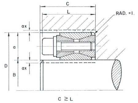
The tapered surfaces of the locking assembly form an angle of approximately 28. The inner and outer rings are split. Consequently, only minor clamping movements and forces are required for radial deformation. For this reason, relatively large deviations from nominal sizes can be bridged without significant torque losses. To prevent excessive distortion of the double tapered thrust rings and to ensure correct functioning of the locking assemblies, it is essential that the assembly is symmetrically located in the annular ring 'a' as shown in the diagram above. When nominal shaft and hub bore sizes are used, this condition automatically exists. Deviations resulting from machining tolerances specified above are easily absorbed by the locking assembly without regard to symmetrical location.
With sizes which deviate from nominal sizes within the limits given in the last column of the table above, it is essential that a smaller diameter shaft be matched with an equivalently larger hub bore or vice versa, thus maintaining locking assembly symmetry within the annular ring 'a'. For example, if the selected shaft diameter B is 0,152 mm undersize, then the hub bore D must be 0,152 mm oversize, i.e. dimensions 'ax' above must be equal within the deviation limits given. When the shaft and hub bore dimensions have been determined, the specified machining tolerances shall be applied.
Required surface finish for shaft and hub bore is NIO i.e. 12,5m
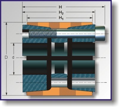
Technical Features
DIMENSIONS |
SCREWS CLASS 12 |
VALUES |
|||||||
d x D |
H1 |
H |
N |
Type |
MA |
Mt |
Pax |
Pw |
Pn |
70 x 110 |
50 |
60 |
8 |
M 10x50 |
|
715 |
20.400 |
19,4 |
10,7 |
80 x 120 |
50 |
60 |
10 |
M 10x50 |
8,3 |
1.025 |
25.400 |
21,2 |
12,3 |
90 x 130 |
50 |
60 |
11 |
M 10x50 |
|
1.260 |
28.000 |
20,7 |
12,5 |
100 x 145 |
60 |
70 |
10 |
M 12x60 |
|
1.860 |
37.200 |
20,5 |
12,6 |
110 x 155 |
60 |
70 |
10 |
M 12x60 |
14,5 |
2.050 |
37.200 |
18,7 |
11,8 |
120 x 165 |
60 |
70 |
11 |
M 12x60 |
|
2.450 |
40.800 |
18,8 |
12,2 |
130 x 180 |
65 |
79 |
14 |
M 12x65 |
|
3.380 |
52.000 |
19,7 |
12,8 |
140 x 190 |
65 |
79 |
15 |
M 12x65 |
14,5 |
3.900 |
55.700 |
19,6 |
12,0 |
150 x 200 |
65 |
79 |
15 |
M 12x65 |
|
4.750 |
55.700 |
18,3 |
12,3 |
160 x 210 |
65 |
79 |
16 |
M 12x65 |
|
4.500 |
59.300 |
18,3 |
12,5 |
170 x 225 |
78 |
92 |
15 |
M 14x75 |
23 |
6.200 |
76.400 |
19,3 |
13,3 |
180 x 235 |
78 |
92 |
15 |
M 14x75 |
|
6.700 |
76.500 |
18,2 |
12,7 |
190 x 250 |
88 |
102 |
16 |
M 14x80 |
23 |
7.000 |
81.500 |
16,3 |
10,3 |
200 x 260 |
88 |
102 |
18 |
M 14x80 |
|
10.300 |
102.000 |
19,4 |
12,4 |
220 x 285 |
96 |
108 |
15 |
M 16x90 |
|
11.200 |
106.000 |
17,4 |
11,3 |
240 x 305 |
96 |
108 |
20 |
M 16x90 |
35,5 |
17.900 |
141.000 |
21,2 |
14,0 |
260 x 325 |
96 |
108 |
21 |
M 16x90 |
|
19.300 |
148.000 |
20,5 |
13,8 |
280 x 355 |
96 |
110 |
15 |
M 20x90 |
69 |
23.200 |
165.000 |
21,3 |
14,1 |
300 x 375 |
96 |
110 |
15 |
M 20x90 |
|
24.900 |
165.000 |
19,8 |
13,4 |
320 x 405 |
124 |
136 |
20 |
M 20x110 |
69 |
35.400 |
221.000 |
19,1 |
12,5 |
340 x 425 |
124 |
136 |
20 |
M 20x110 |
|
37.600 |
221.000 |
18,0 |
11,9 |
360 x 455 |
140 |
155 |
20 |
M 22x130 |
|
49.600 |
275.000 |
18,5 |
11,8 |
380 x 475 |
140 |
155 |
20 |
M 22x130 |
|
52.400 |
275.000 |
17,5 |
11,3 |
400 x 495 |
140 |
155 |
22 |
M 22x130 |
|
60.200 |
301.000 |
18,3 |
12,2 |
420 x 515 |
140 |
155 |
24 |
M 22x130 |
|
69.400 |
330.000 |
19,0 |
12,7 |
440 x 535 |
140 |
155 |
24 |
M 22x130 |
|
72.800 |
330.000 |
16,6 |
12,3 |
460 x 555 |
140 |
155 |
24 |
M 22x130 |
|
76.000 |
330.000 |
15,9 |
11,8 |
480 x 575 |
140 |
155 |
25 |
M 22x130 |
93 |
83.000 |
344.000 |
15,9 |
11,9 |
500 x 596 |
140 |
155 |
25 |
M 22x130 |
|
86.100 |
344.000 |
15,3 |
11,5 |
520 x 615 |
140 |
155 |
28 |
M 22x130 |
|
100.300 |
385.000 |
16,4 |
12,4 |
540 x 625 |
140 |
155 |
28 |
M 22x130 |
|
104.200 |
385.000 |
15,8 |
12,0 |
560 x 655 |
140 |
155 |
30 |
M 22x130 |
|
115.700 |
413.000 |
16,3 |
12,5 |
580 x 675 |
140 |
155 |
30 |
M 22x130 |
|
119.900 |
413.000 |
15,8 |
12,1 |
600 x 695 |
140 |
155 |
30 |
M 22x130 |
|
124.000 |
413.000 |
15,3 |
11,8 |
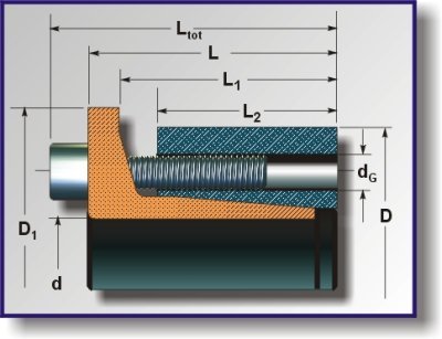
Locking Assemblies RINGFEDER RfN 7013.1
For shaft diameters 160mm up to 300mm
| Locking Assembly dimensions | Transmissible | Surface pressure between Locking and Assembly and | Locking screws DIN 912-12.9 | ||||||||||
| d x D | Ltot | L | L1 | L2 | D1 | torques | axial loads | shaft | hub | Qty. | Thread | TA | Weight |
| T | F | p | p1 | dG | |||||||||
| mm | mm | mm | Nm | kN | N/mm2 | Nm | Kg | ||||||
| 160 x 210 | 77 | 65 | 53 | 45,4 | 220 | 34000 | 425 | 300 | 131 | 20 | M 12 x 40 | 145 | 7,2 |
| 170 x 225 | 89 | 75 | 61 | 51 | 235 | 39600 | 465 | 184 | 120 | 16 | M 14 x 50 | 230 | 9,5 |
| 180 x 235 | 89 | 75 | 61 | 51 | 245 | 47000 | 522 | 195 | 130 | 18 | M 14 x 50 | 230 | 10 |
| 190 x 250 | 99 | 85 | 71 | 61,4 | 260 | 5540 | 583 | 171 | 112 | 20 | M 14 x 50 | 230 | 13 |
| 200 x 260 | 99 | 85 | 71 | 61,4 | 270 | 58300 | 583 | 163 | 108 | 20 | M 14 x 50 | 230 | 14 |
| 220 x 285 | 111 | 95 | 79 | 65 | 295 | 71400 | 649 | 155 | 103 | 16 | M 16 x 60 | 355 | 18 |
| 240 x 305 | 111 | 95 | 79 | 65 | 315 | 9700 | 808 | 178 | 121 | 20 | M 16 x 60 | 355 | 20 |
| 260 x 325 | 111 | 95 | 79 | 65 | 335 | 116000 | 892 | 181 | 125 | 22 | M 16 x 60 | 355 | 22 |
| 280 x 355 | 121 | 105 | 90 | 75 | 365 | 142000 | 1014 | 160 | 113 | 25 | M 16 x 60 | 355 | 30 |
| 300 x 375 | 121 | 105 | 90 | 75 | 385 | 170000 | 1133 | 167 | 119 | 28 | M 16 x 60 | 355 | 32 |
Explanations |
Mounting of Locking Assembly: |
|
d x D, D1, Ltot, L, L1, L2 = |
The values for T, Fax, p and p' apply to Locking Assemblies installed in an oiled condition. |
|
Basic dimensions, Locking Assemblies not tightened |
||
dG = |
|
|
T = |
Surface finishes: |
|
Transmissible torque |
For shafts and hub bores: |
|
Fax = |
Rt < 10 m (< 0,010 mm) |
|
Transmissible axial load |
|
|
p = |
Tolerances: |
|
Maximum surface pressure between Locking Assembly and shaft |
We recommend the following tolerances |
|
p' = |
shaft: h8 |
hub: H8 |
Maximum surface pressure between Locking Assembly and shaft |
|
|
TA = |
Changing of the screw tightening moments: |
|
Maximum tightening torque for the screws considered in order to determine the values T, Fax, p and p'. |
A change of the TA values of the above table is inadmissible. |
|
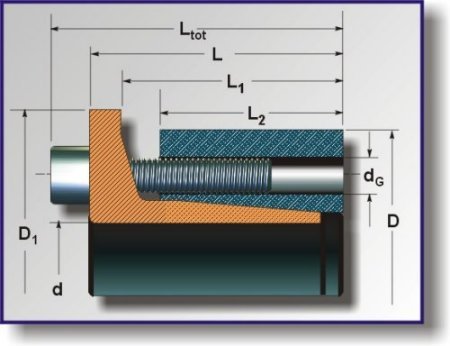
Supplement to CATALOG S77E
Locking Assembly dimensions |
Transmissible |
Surface Pressure between Locking Assembly and |
Locking screws DIN 912-12.9 |
|
|||||||||
d x D |
Ltot |
L |
L1 |
L2 |
D1 |
Torques |
Axial loads |
Shaft p |
Hub p' |
Thread |
Weight kg |
||
T or Nm |
Fax kN |
N/mm2 |
Qty. |
dG |
TA Nm |
||||||||
40x65 |
33,5 |
27,5 |
22 |
18 |
73 |
940 |
45 |
215 |
118 |
10 |
M 6x20 |
17 |
0,38 |
45x75 |
41 |
33 |
25 |
20 |
83 |
1860 |
80 |
314 |
169 |
9 |
M 8x25 |
41 |
0,63 |
50x80 |
41 |
33 |
25 |
20 |
88 |
2070 |
80 |
283 |
160 |
9 |
M 8x25 |
41 |
0,68 |
55x85 |
41 |
33 |
25 |
20 |
95 |
2540 |
90 |
300 |
175 |
10 |
M 8x25 |
41 |
0,73 |
60x90 |
41 |
33 |
25 |
20 |
100 |
2770 |
90 |
274 |
165 |
10 |
M 8x25 |
41 |
0,78 |
65x95 |
41 |
33 |
25 |
20 |
105 |
3580 |
105 |
290 |
178 |
12 |
M 8x25 |
83 |
0,83 |
70x110 |
50 |
40 |
30 |
23 |
120 |
5100 |
140 |
315 |
186 |
10 |
M 10x35 |
83 |
1.3 |
75x115 |
50 |
40 |
30 |
23 |
125 |
5460 |
140 |
294 |
173 |
10 |
M 10x35 |
83 |
1.4 |
80x120 |
50 |
40 |
30 |
23 |
130 |
5850 |
140 |
276 |
163 |
10 |
M 10x35 |
83 |
1.5 |
85x125 |
50 |
40 |
30 |
23 |
135 |
7450 |
175 |
297 |
187 |
12 |
M 10x35 |
83 |
1.55 |
90x130 |
50 |
40 |
30 |
23 |
140 |
7900 |
175 |
280 |
180 |
12 |
M 10x35 |
83 |
1.65 |
95x135 |
50 |
40 |
30 |
23 |
145 |
9900 |
205 |
330 |
217 |
15 |
M 10x35 |
83 |
1.7 |
100x145 |
52,5 |
42,5 |
32 |
25 |
155 |
11000 |
220 |
290 |
186 |
15 |
M 10x35 |
83 |
2.6 |
110x155 |
52,5 |
42,5 |
32 |
25 |
165 |
12100 |
220 |
264 |
175 |
15 |
M 10x35 |
83 |
2.8 |
120x165 |
52,5 |
42,5 |
32 |
25 |
175 |
15700 |
260 |
290 |
196 |
18 |
M 10x35 |
83 |
3.0 |
130x180 |
65 |
53 |
40 |
33 |
190 |
20700 |
320 |
238 |
165 |
15 |
M 12x40 |
145 |
4.6 |
140x190 |
65 |
53 |
40 |
33 |
200 |
22500 |
320 |
222 |
157 |
15 |
M 12x40 |
145 |
4.9 |
150x200 |
65 |
53 |
40 |
33 |
210 |
28500 |
380 |
249 |
179 |
18 |
M 12x40 |
145 |
5.2 |
160x210 |
65 |
53 |
40 |
33 |
220 |
34000 |
425 |
275 |
183 |
20 |
M 14x50 |
230 |
5.5 |
170x225 |
78 |
64 |
50 |
40 |
235 |
39600 |
465 |
231 |
153 |
16 |
M 14x50 |
230 |
7.8 |
180x235 |
78 |
64 |
50 |
40 |
245 |
47000 |
522 |
245 |
166 |
18 |
M 14x50 |
230 |
8.2 |
190x250 |
78 |
64 |
50 |
40 |
260 |
55400 |
583 |
252 |
172 |
20 |
M 14x50 |
230 |
9.5 |
200x260 |
78 |
64 |
50 |
40 |
270 |
58300 |
583 |
240 |
166 |
20 |
M 16x60 |
355 |
9.9 |
220x285 |
88 |
72 |
56 |
42 |
295 |
71400 |
649 |
235 |
160 |
16 |
M 16x60 |
355 |
13.4 |
240x305 |
88 |
72 |
56 |
42 |
315 |
97000 |
808 |
269 |
188 |
20 |
M 16x60 |
355 |
14.3 |
260x325 |
88 |
72 |
56 |
42 |
335 |
116000 |
892 |
274 |
194 |
22 |
M 16x60 |
355 |
15.5 |
280x355 |
98 |
82 |
66 |
51 |
365 |
142000 |
1014 |
228 |
166 |
25 |
M 16x60 |
355 |
22.9 |
300x375 |
98 |
82 |
66 |
51 |
385 |
170000 |
1133 |
238 |
175 |
28 |
M 16x60 |
355 |
24.4 |
FOR SIZES OTHER THAN THOSE SHOWN PLEASE CONTACT OUR TECHNICAL DEPARTMENT.
DOUBLE TAPERED LOCKING ASSEMBLY TYPE RFN 3012
Dimensions |
Performances |
Pressure |
Clamping screws DIN 912-12.9 |
||||||
d x D |
H2 |
H |
H1 |
Mt |
Pax |
Pw |
Pn |
size |
Ms |
45 x 75 |
72 |
56 |
64 |
385 |
17.200 |
18.4 |
10.9 |
M 8 |
4.1 |
48 x 80 |
72 |
56 |
64 |
410 |
17.200 |
16.9 |
10.4 |
M8 |
4.1 |
50 x 80 |
72 |
56 |
64 |
425 |
17.200 |
16.4 |
10.4 |
M 8 |
4.1 |
55 x 85 |
72 |
56 |
64 |
475 |
17.200 |
14.9 |
9.4 |
M 8 |
4.1 |
60 x 90 |
72 |
56 |
64 |
635 |
21.100 |
16.9 |
10.9 |
M 8 |
4.1 |
65 x 95 |
72 |
56 |
64 |
685 |
21.100 |
15.4 |
10.4 |
M 8 |
4.1 |
70 x 110 |
88 |
70 |
78 |
1.175 |
33.600 |
18.4 |
11.4 |
M 10 |
8.3 |
75 x 115 |
88 |
70 |
78 |
1.265 |
33.600 |
16.9 |
10.9 |
M 10 |
8.3 |
80 x 120 |
88 |
70 |
78 |
1.465 |
36.700 |
17.4 |
11.4 |
M 10 |
8.3 |
85 x 125 |
88 |
70 |
78 |
1.565 |
36.700 |
16.4 |
10.9 |
M 10 |
8.3 |
90 x 130 |
88 |
70 |
78 |
1.795 |
39.800 |
16.9 |
11.4 |
M 10 |
8.3 |
95 x 135 |
88 |
70 |
78 |
1.895 |
39.800 |
15.9 |
10.9 |
M 10 |
8.3 |
100 x 145 |
112 |
90 |
100 |
2.685 |
53.600 |
15.9 |
10.9 |
M 12 |
14.5 |
110 x 155 |
112 |
90 |
100 |
3.195 |
58.100 |
15.4 |
10.9 |
M 12 |
14.5 |
120 x 165 |
112 |
90 |
100 |
4.025 |
67.100 |
16.4 |
11.9 |
M 12 |
14.5 |
130 x 180 |
128 |
104 |
116 |
5.195 |
79.800 |
15.4 |
11.4 |
M 14 |
23 |
140 x 190 |
130 |
104 |
116 |
6.455 |
92.100 |
16.9 |
12.4 |
M 14 |
23 |
150 x 200 |
130 |
104 |
116 |
7.375 |
98.300 |
16.4 |
12.4 |
M 14 |
23 |
160 x 210 |
130 |
104 |
116 |
8.365 |
104.300 |
16.4 |
12.4 |
M 14 |
23 |
170 x 225 |
162 |
134 |
146 |
10.895 |
128.100 |
14.9 |
11.4 |
M 16 |
35.5 |
180 x 235 |
162 |
134 |
146 |
12.315 |
136.700 |
14.9 |
11.4 |
M 16 |
35.5 |
190 x 250 |
162 |
134 |
146 |
13.795 |
145.200 |
14.9 |
11.4 |
M 16 |
35.5 |
200 x 260 |
162 |
134 |
146 |
14.535 |
145.200 |
14.4 |
10.9 |
M 16 |
35.5 |
220 x 285 |
162 |
134 |
146 |
18.795 |
170.800 |
15.4 |
11.9 |
M 16 |
35.5 |
240 x 305 |
162 |
134 |
146 |
22.495 |
187.800 |
15.4 |
11.9 |
M 16 |
35.5 |
260 x 325 |
162 |
134 |
146 |
24.395 |
187.800 |
14.4 |
11.4 |
M 16 |
35.5 |
280 x 355 |
197 |
165 |
177 |
37.295 |
266.800 |
15.4 |
11.9 |
M 20 |
69 |
300 x 375 |
197 |
165 |
177 |
43.994 |
292.800 |
15.4 |
12.4 |
M 20 |
69 |
320 x 405 |
197 |
165 |
177 |
46.995 |
292.800 |
14.4 |
11.4 |
M 20 |
69 |
340 x 425 |
197 |
165 |
177 |
54.400 |
320.000 |
14.9 |
11.9 |
M 20 |
69 |
360 x 455 |
224 |
190 |
202 |
65.800 |
365.000 |
13.9 |
10.9 |
M 22 |
93 |
380 x 475 |
224 |
190 |
202 |
82.100 |
432.000 |
15.9 |
12.9 |
M 22 |
93 |
400 x 495 |
224 |
190 |
202 |
86.400 |
432.000 |
14.9 |
11.9 |
M 22 |
93 |
420 x 515 |
224 |
190 |
202 |
90.700 |
432.000 |
14.4 |
11.9 |
M 22 |
93 |
440 x 535 |
224 |
190 |
202 |
95.000 |
432.000 |
13.9 |
11.4 |
M 22 |
93 |
460 x 555 |
224 |
190 |
202 |
99.300 |
432.000 |
12.9 |
10.9 |
M 22 |
93 |
480 x 575 |
224 |
190 |
202 |
119.600 |
498.000 |
14.4 |
11.9 |
M 22 |
93 |
500 x 596 |
224 |
190 |
202 |
124.600 |
498.000 |
13.9 |
11.9 |
M 22 |
93 |
520 x 615 |
224 |
190 |
202 |
138.200 |
531.000 |
13.9 |
11.9 |
M 22 |
93 |
540 x 625 |
224 |
190 |
202 |
143.600 |
531.000 |
13.9 |
11.9 |
M 22 |
93 |
560 x 655 |
224 |
190 |
202 |
158.200 |
565.000 |
13.9 |
11.9 |
M 22 |
93 |
580 x 675 |
224 |
190 |
202 |
163.800 |
565.000 |
13.4 |
11.4 |
M 22 |
93 |
600 x 695 |
224 |
190 |
202 |
169.500 |
565.000 |
12.9 |
10.9 |
M 22 |
93 |
Legend
Ms (daNm):
Screws tightening torque
Mt (daNm):
Transmissible torque
Pax (daN):
Transmissible axial force
Pw (daN/mm):
Shaft surface pressure
Pn (daN/mm):
Hub surface pressure
RINGFEDER TYPE 40 RIGID FLANGE COUPLING FOR KEYLESS SHAFTS
- Ringfeder Rigid Flange coupling Type 40, locally manufactured to the German DIN spec ideal for shaft mounting drives.
- Hollow shaft gearboxes are out. Ringfeder flange mounting is in. no more burning of shafts to change bearings.
- No maintenance, no keyway, shaft diameters can be reduced by up to 30%. The proven one - To change drives, is so simple - Just fit and forget.
- Fitted with RFN 3012 self-centring imported locking elements.
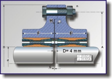
RINGFEDER/STUWE TRUE RUNNING RIGID FLANGE COUPLING FOR SIMILTANEOUS TORQUE TRANSMISSION AND BENBING
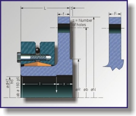
Tpye |
dw |
Mt max |
MD |
N |
R |
L |
l |
f |
t |
Shrink disc size |
X |
FK RAG 400-100 |
95 |
15100 |
4500 |
400 |
300 |
104 |
55 |
30 |
6 |
140-71 |
32 |
105 |
20100 |
||||||||||
FK RAG 400-110 |
105 |
22000 |
6000 |
400 |
300 |
108 |
59 |
30 |
6 |
155-71 |
32 |
115 |
28000 |
||||||||||
FK RAG 400-120 |
115 |
31000 |
7800 |
400 |
300 |
114 |
65 |
30 |
6 |
165-71 |
34 |
125 |
39000 |
||||||||||
FK RAG 400-130 |
125 |
40000 |
10000 |
400 |
300 |
114 |
73 |
30 |
6 |
175-71 |
34 |
140 |
52000 |
Tpye |
dw |
Mt max |
MD |
N |
R |
L |
l |
f |
t |
Shrink disc size |
X |
FK RAG 560-150 |
145 |
72000 |
15200 |
560 |
280 |
139 |
81 |
36 |
8 |
200-71 |
38 |
160 |
90000 |
||||||||||
FK RAG 560-170 |
160 |
100000 |
18500 |
560 |
280 |
157 |
98 |
36 |
8 |
220-71 |
38 |
170 |
116000 |
||||||||||
FK RAG 560-190 |
170 |
120000 |
26200 |
560 |
280 |
161 |
104 |
36 |
8 |
240-71 |
38 |
190 |
158000 |
||||||||||
FK RAG 560-210 |
190 |
164000 |
36000 |
560 |
280 |
184 |
115 |
36 |
8 |
260-71-3 |
38 |
210 |
204000 |
Tpye |
dw |
Mt max |
MD |
N |
R |
L |
l |
f |
t |
Shrink disc size |
X |
FK RAG 630-200 |
190 |
164000 |
36000 |
630 |
350 |
188 |
115 |
40 |
8 |
260-71 |
38 |
210 |
204000 |
||||||||||
FK RAG 630-220 |
210 |
217000 |
48000 |
630 |
350 |
196 |
126 |
40 |
8 |
280-71 |
42 |
230 |
273000 |
||||||||||
FK RAG 630-240 |
230 |
262000 |
62200 |
630 |
350 |
204 |
136 |
40 |
8 |
300-71 |
42 |
245 |
308000 |
Tpye |
dw |
Mt max |
MD |
N |
R |
L |
l |
f |
t |
Shrink disc size |
X |
FK RAG 710-260 |
250 |
394000 |
79000 |
710 |
550 |
220 |
148 |
40 |
8 |
340-71 |
42 |
270 |
466000 |
Mt (Max transmittable torque)
Mb (Max bending moment not to be exceeded)
RIBGFEDER TYPE 30 RIGID FLANGE COUPLING
- Ringfeder Rigid Flange coupling Type 30, locally manufactured to the German DIN spec ideal for shaft mounting drives.
- Hollow shaft gearboxes are out. Ringfeder flange mounting is in. no more burning of shafts to change bearings.
- No maintenance, no keyway, shaft diameters can be reduced by up to 30%. The proven one - To change drives, is so simple - Just fit and forget.
- Out of all other flange couplings it is the only one that can be easily removed
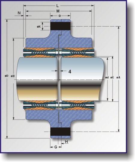
Click Here For Table
