Sole Plates
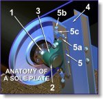
Anatomy of a sole plate
For the purpose of clarity the following diagram indicates a typical sole plate installed for a conveyor pulley bearing support assembly.
Click on the thumbnail for a larger image.
The conveyor pulley shaft (1) is supported in a bearing (2) by means of a plummer block (3). The plummer block is then bolted to the support structure (4) however, the base of the plummer block is seated onto a sole plate (5).
The sole plate comprises a machined steel plate (5a) which is tack welded to the support structure (4), jacking bolts (5b) and lock nuts (5c).
The jacking bolts are used to align the pulley horizontally before the plummer block securing bolts are finally tightened.
Should shims be required for packing under one of the plummer blocks, these are inserted between the sole plate and plummer block for finer pulley alignment.
