| Pulley Bearings |
|
Pulley Bearing Basics
a) Anatomy of a pulley bearing
For the purpose of clarity the following diagram indicates the typical pulley assembly, showing the support bearing arrangement comprising bearings, plummer blocks and sole plates. Click on the thumbnail for larger image.
The conveyor pulley shell (1) is fixed to the pulley shaft (2) by means of locking elements (3). The shaft is supported in bearings (4) which are housed in plummer blocks (5) to enable the pulley to rotate freely. The plummer blocks are secured on sole plates (6) which are welded to the pulley support structure (7). The sole plates enable the pulley to be aligned by adjusting the jacking screws (8).
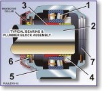
In more specific detail, a typical bearing and plummer block assembly (SKF) is indicated below (click on thumbnail for larger image) :-
The tapered spherical roller bearing pulley bearing (1) is shown attached to the pulley supporting stub shaft (2) by means of an adapter sleeve (3) and lock nut (4). The plummer block or bearing housing (5) supports the bearing. Item (6) is a typical sealing arrangement and (7) is the end cap.
A number of variations to this arrangement are available, depending on the application, environment.
b) Types and arrangement of pulley bearings
Bearings used for conveyor pulleys are generally spherical roller bearings, chosen for their radial and axial load supporting characteristics.
The bearings are self-aligning relative to their raceways, which means that the bearings can be 'misaligned' relative to the shaft and plummer blocks, to a certain degree. In practical terms this implies that the bending of the shaft under loaded conditions as well as minor misalignment of the pulley support structure, can be accommodated by the bearing.
It is generally accepted that pulley shafts must comprise one 'fixed' or 'located' bearing assembly, and one 'floating' of 'non-located' bearing.
The 'located' bearing assembly ensures that the axial position of the shaft relative to the bearing housing can be determined and once installed, cannot be changed. When the conveyor is operating, the shaft is therefore unable to move axially.
The 'floating' bearing assembly on the other hand enables the bearing to be located almost anywhere along the shaft, and once installed, the bearing is able to move relative to the bearing housing.
These design features enable the pulleys to be installed onto the conveyor structures and correctly aligned without the need for absolute accuracy in the setting up and installation process.
Another feature of pulley bearing assemblies is the adaptor and withdrawal sleeves. Adapter sleeves are used to secure tapered bore bearings to cylindrical shafts seatings.
The advantages of using the adapter sleeves is the ease with which the bearing can be mounted onto the shaft in either the 'fixed' or 'floating' application.
The adapter sleeve is first mounted onto the shaft, followed by the bearing and a lock nut to secure the bearing to the shaft.
In the case of withdrawal sleeves, the removal of the bearing is made simpler however in order to use a withdrawal sleeve, the shaft should have a shoulder or positive locating means plus a threaded section to enable the bearing to be firmly fixed into position.
In both cases where either adapter or withdrawal sleeves are employed, the machining tolerances on the shaft can be relaxed as the sleeves essentially compensate for irregularities.
Bearings for pulleys can be supplied with seals and greasing ports or without these facilities, depending on the application. These seals are generally in addition to the seals provided on the plummer bocks and are used in cases where the environment is particularly harsh such as high moisture / water conditions, or particularly dusty conditions.
A number of variations are available from the different suppliers.
c) Layout
Bearings are usually mounted onto pulley shafts at pre-defined spacings, which is the norm followed in the industry.
Factors which affect the bearing centers include the width of the conveyor belt and hence pulley shell, the width of the (discharge) chute work, the design of the pulley support structure and whether or not the pulley is a take-up pulley, tail pulley or drive pulley.
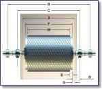
The standard bearing spacing followed is as per the table below :-
| Belt width | Face width | Chute plates I/S | Bearing centres | Clearances for wide
centres See legend below |
|||
| Wide | Narrow | ||||||
| W | F | A | B | C | D | E | G |
| 450 | 550 | 650 | 1000 | 760 | 225 | 50 | 50 |
| 500 | 600 | 700 | 1050 | 810 | 225 | 50 | 50 |
| 600 | 700 | 800 | 1150 | 1020 | 225 | 50 | 50 |
| 750 | 900 | 1000 | 1350 | 1170 | 225 | 75 | 50 |
| 900 | 1050 | 1150 | 1550 | 1370 | 250 | 75 | 50 |
| 1050 | 1200 | 1300 | 1700 | 1520 | 250 | 75 | 50 |
| 1200 | 1350 | 1450 | 1850 | 1680 | 250 | 75 | 50 |
| 1350 | 1500 | 1600 | 2050 | 1830 | 275 | 75 | 50 |
| 1500 | 1700 | 1850 | 2300 | 1980 | 300 | 100 | 75 |
| 1650 | 1850 | 2000 | 2450 | 2130 | 300 | 100 | 75 |
| 1800 | 2000 | 2150 | 2600 | 2280 | 300 | 100 | 75 |
| 2100 | 2300 | 2450 | 2900 | 2580 | 300 | 100 | 75 |
| 2400 | 2600 | 2750 | 3200 | 2880 | 300 | 100 | 75 |
Legend :-
D = Pulley face to centre-line bearing housing.
E = Pulley face to belt edge.
G = Pulley face to inside chute plate.


