| Beginners Guide |
|
2. Basics of Troughed Conveyor Pulleys
This section deals exclusively with pulleys for troughed belt conveyors.
a) Functional description
Pulleys are used on conveyors to support and deflect the belting through the conveyor structure.
Pulleys also provide a mechanism whereby the conveyor belt can be trained to run (track) true along the conveyor idlers.
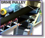
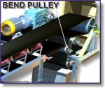
The following graphic indicates the location of pulleys on a conveyor.
Generally, pulleys are located at the ends of the conveyor structure and at the take-up arrangement. Pulleys are used to transmit the drive power into the conveyor belt and as such, are subjected to the dynamic belt tension forces in a conveyor.
There are a number of different types of pulleys available for use on conveyors as well as different design parameters for pulleys serving different functions on the same conveyor.
To see examples of pulleys on a conveyor, click on the thumbnails below :-
 |
 |
 |
 |
 |
|
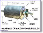
b) Anatomy of a conveyor pulley
A typical pulley is shown in the following picture :-
The components of a pulley include the following :-
| Drum or Shell | The drum is the portion of the pulley in direct contact with the belt. The shell is fabricated from either a rolled sheet of steel or from hollow steel tubing.
The shell has a specific 'face' width and diameter which is determined by the width of the belting and the type and rating of the belt to be used on the conveyor. |
|
| Diaphragm Plates | The diaphragm or end plates of a pulley are circular discs which are fabricated from thick steel plate and which are welded into the shell at each end, to strengthen the drum.
The end plates are bored in their centre to accommodate the pulley shaft and the hubs for the pulley locking elements. |
|
| Shaft | The shaft is designed to accommodate all the applied forces from the belt and / or the drive unit, with minimum deflection.
The shaft is located and locked to the hubs of the end discs by means of a locking elements. Shafts often comprise different diameters along their length due to the bending moments and resultant deflection limitations. The diameter of the shaft at the landings for the bearings may be smaller to satisfy the necessary bearing diameter which is more cost-effective (smaller). Similarly in the case of a drive shaft, the drive attachment, may be different to the other diameters along the shaft and hence pulley shafts are often stepped. |
|
| Locking Elements | These are high-precision manufactured items which are fitted over the shaft and into the pulley hubs. The locking elements attach the pulley firmly to the shaft via the end plates.
Locking elements (see adjacent image) work on the friction-grip principle whereby the element is able to be fastened to the shaft and hub simultaneously and concentrically, by tightening a series of screws around the locking element. |
|
| Hubs | The hubs are fabricated and machined housings which are welded into the end plates. The hubs are sized according to the size of the pulley, the diameter of the shaft and the size of the locking element which is required for the specific duty. | |
| Lagging | It is sometimes necessary or desirable to improve the friction between the conveyor belt and the pulley in order to improve the torque that can be transmitted through a drive pulley.
Improved traction over a pulley also assists with the training of the belt. In such cases pulley drum surfaces are 'lagged' or covered in a rubberized material. This cover is usually 8 mm to 12 mm thick and can be plain or have a grooved pattern. The rubber lagging is vulcanized to the pulley shell to ensure that it remains attached under adverse operating conditions. |
|
| Bearing Assemblies | Bearings support the rotating shaft and hence the pulley. The bearings are housed in 'plummer blocks' which enable the mass of the pulley assembly plus the belt tension forces to be transmitted to the pulley supporting structure.
Plummer blocks are often bolted to 'sole plates' which are welded to the structure. The sole plates incorporate jacking screws to enable the pulley to be correctly and relatively easily aligned. |
|
c) Types of pulleys
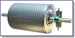
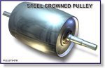
Historically there has always been a number of different types of pulleys ranging from cast iron pulleys to slatted pulleys, crowned pulleys and fabricated steel pulleys as described above.
It is common practice today to make use of steel pulleys throughout a conveyor. Exceptions to this standard are mainly for cases where a conveyors' discharge point is equipped with a magnetic separator over the head pulley. In this case the pulley shell and end plates are usually manufactured in non-magnetic stainless steel.
Crowned pulleys are however still used and the following thumbnails indicate the different types of pulleys in use.
Click on the thumbnails for larger images :-
 |
 |
 |
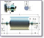
d) Terminology
Whenever the details of pulleys, shafts and bearing assemblies are discussed by designers, it is important that the terminology used is clearly understood.
The basic terminology is outlined in this sketch for clarity.
| A | Bearing housing centres |
| B | Shaft extension - drive |
| C | Shaft extension - brake/holdback |
| D | Pulley diameter |
| d1 | Shaft diameter - locking elements |
| d2 | Shaft diameter - bearing |
| d3 | Shaft diameter - drive |
| d4 | Shaft diameter - brake/holdback |
| E | Drive landing length |
| F | Brake/holdback landing length |
| G | Keyway length - brake/holdback |
| H | Keyway length - drive |
| L | Overall shaft length |
| M | Step length |
| R | Minimum machined radius |
| V | Keyway depth - drive |
| W | Keyway width - drive |
![]()