| Plummer Blocks |
|
Anatomy of pulley plummer block assemblies
For the purpose of clarity the following diagram indicates the typical pulley assembly, showing the support bearing arrangement comprising bearings, plummer blocks and sole plates. Click on the thumbnail for larger image.
The conveyor pulley shell (1) is fixed to the pulley shaft (2) by means of locking elements (3). The shaft is supported in bearings (4) which are housed in plummer blocks (5) to enable the pulley to rotate freely. The plummer blocks are secured on sole plates (6) which are welded to the pulley support structure (7). The sole plates enable the pulley to be aligned by adjusting the jacking screws (8).
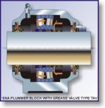
In more specific detail, a typical bearing and plummer block assembly (SKF) is indicated below (click on thumbnail for larger image):-


