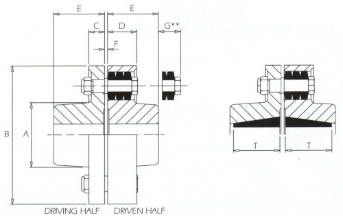
COUPLINGS DIMENSIONS & PIN AND CONE RING DIMENSIONS
Table 15 - Coupling Dimensions (mm)
Coupling size column entry 5 & 6 |
Types 611 & 612 Straight bored |
Types 613 & 614 Taper bushed |
|||||||||||||||
Max. bore |
Min. bore * |
Hub length E |
G ** |
Max. bore |
Min. bore |
Hub length E |
Bush length T |
G ** |
A |
B |
C |
D |
F |
No of pins |
|||
Driving half |
Driven half |
Medium Duty |
Heavy Duty |
||||||||||||||
01 |
38 |
* |
19 |
48 |
20 |
25 |
9 |
40 |
22.3 |
28 |
64 |
134 |
12 |
26 |
3 |
3 |
6 |
02 |
42 |
* |
22 |
56 |
12 |
Not available as taper bushed |
70 |
147 |
12 |
26 |
3 |
4 |
8 |
||||
03 |
48 |
* |
25 |
61 |
26 |
40 |
14 |
50 |
38.1 |
37 |
83 |
171 |
19 |
35 |
3 |
3 |
6 |
04 |
60 |
* |
28 |
68 |
19 |
Not available as taper bushed |
97 |
193 |
19 |
35 |
3 |
4 |
8 |
||||
05 |
70 |
* |
32 |
76 |
11 |
60 |
16 |
50 |
44.5 |
37 |
117 |
215 |
19 |
35 |
3 |
5 |
10 |
06 |
80 |
28 |
42 |
88 |
46 |
Not available as taper bushed |
127 |
254 |
31 |
56 |
3 |
4 |
8 |
||||
07 |
90 |
35 |
55 |
100 |
34 |
75 |
35 |
82 |
76.2 |
52 |
147 |
279 |
31 |
56 |
3 |
5 |
10 |
08 |
100 |
40 |
60 |
117 |
22 |
90 |
35 |
98 |
88.9 |
41 |
180 |
330 |
31 |
61 |
3 |
6 |
12 |
09 |
120 |
50 |
65 |
132 |
45 |
110 |
55 |
124 |
114.3 |
53 |
206 |
371 |
46 |
81 |
6 |
5 |
10 |
10 |
140 |
80 |
147 |
30 |
125 |
70 |
136 |
127 |
41 |
230 |
419 |
46 |
81 |
6 |
6 |
12 |
|
11 |
150 |
90 |
165 |
12 |
Not available as taper bushed |
256 |
457 |
46 |
81 |
6 |
7 |
14 |
|||||
12 |
170 |
100 |
188 |
0 |
296 |
533 |
46 |
81 |
6 |
9 |
18 |
||||||
13 |
180 |
As required |
211 |
28 |
330 |
597 |
104 |
109 |
6 |
6 |
12 |
||||||
14 |
200 |
236 |
10 |
368 |
660 |
104 |
109 |
6 |
7 |
14 |
|||||||
15 |
230 |
264 |
43 |
406 |
737 |
140 |
140 |
6 |
6 |
12 |
|||||||
16 |
255 |
292 |
15 |
457 |
826 |
140 |
140 |
6 |
7 |
14 |
|||||||
17 |
280 |
311 |
0 |
508 |
927 |
140 |
140 |
6 |
8 |
16 |
|||||||
18 |
305 |
324 |
0 |
533 |
991 |
140 |
140 |
6 |
9 |
18 |
|||||||
19 |
330 |
330 |
0 |
572 |
1067 |
140 |
140 |
6 |
10 |
20 |
|||||||
20 |
355 |
356 |
0 |
610 |
1156 |
140 |
140 |
6 |
11 |
22 |
|||||||
Notes:
* Up to size 05 the driving half hubs are solid
** The coupling pin withdrawal distance
Notes: (for sizes 13 to 20 only)
The above dimensions are for guidance only
Consult David Brown when an imperial bore and keyway to BS 46 is required in a coupling with near maximum bore. Generally the depth of the keyway is greater than that of the metric keyways, hence the maximum bores given must be marginally reduces

Table 16 - Pin and Cone Ring Dimensions (mm)
Coupling size |
Pin Assembly Number |
Cone Ring Number |
H |
J |
K |
L |
M |
N |
P |
Q |
Max Bolt Tightening Torque (Nm) |
No of Rubber Rings Per Pin |
01-02 |
41111-2-024 |
32213-9-102 |
58 |
M10 |
12.7 |
12.7 |
5.1 |
7.6 |
28.2 |
17 |
15 |
3 |
03-05 |
41111-2-025 |
32213-9-103 |
75 |
M12 |
15.9 |
17.8 |
6.4 |
10.2 |
38.1 |
24 |
25 |
3 |
06-08 |
41111-2-026 |
32213-9-104 |
118 |
M20 |
25.4 |
25.4 |
8.9 |
12.7 |
50.8 |
36 |
115 |
4 |
09-12 |
41111-2-027 |
32213-9-105 |
161 |
M24 |
28.6 |
30.6 |
12.7 |
17.8 |
63.5 |
36 |
200 |
4 |
13-14 |
41111-2-028 |
32213-9-106 |
208 |
M36 |
41.3 |
43.3 |
15.2 |
22.9 |
85.3 |
51 |
140 |
4 |
15-20 |
41111-2-029 |
32213-9-107 |
259 |
M48 |
57.2 |
58.2 |
20.3 |
30.5 |
113.7 |
70 |
334 |
4 |