Useful Conveyor Data
SECTION 1 - MECHANICAL CONVEYING EQUIPMENT
INDEX
STANDARD NO. |
||
CM/0900/ |
BB1 |
Maximum belt speeds |
|
BB2 |
Maximum lump size |
|
||
BC1 |
Conveyor chutes |
|
BC2 |
Discharge chute openings |
|
BC3 |
Chute discharge opening |
|
BC4 |
Langlaagte chute |
|
BC5 |
Adjustable discharge opening |
|
BC6 |
Flop gate |
|
BC7 |
Chute liner materials |
|
BC8 |
Skirtboard details |
|
BC9 |
Bifurcated head chute |
|
|
||
BF1 |
Fabric belt types |
|
BF2 |
Fabric belt strength |
|
BF3 |
Fabric belt width / troughing angles / piles |
|
BF4 |
Fabric belt pulley diameters |
|
BF5 |
Fabric belt tension |
|
BF6 |
Fabric belt impact index |
|
BF7 |
Fabric belt top cover gauge |
|
BF8 |
Fabric belt carcass mass |
|
BF9 |
Fabric belt take-up travel |
|
|
||
BI1 |
Idler spacing |
|
BI2 |
Idler transition distance |
|
BI3 |
Stringer centres |
|
|
||
BS1 |
Steel belt tension |
|
BS2 |
Steel belt pulley diameters |
|
BS3 |
Steel belt mass |
|
BS4 |
Steel belt number of cables |
|
BS5 |
Steel belt splicing length |
|
BS6 |
Steel belt cover selection |
|
|
||
CA1 |
Curved belt geometry, set-out points |
|
CA2 |
Inclined belt set-out points |
|
CA3 |
Change of incline per idler |
|
|
||
CB1 |
Conveyor Bearing Centres |
|
CB2 |
Plummer block selection chart |
|
CB4 |
Belt rating chart |
|
|
||
CC1 |
Areas and capacities - troughed belts |
|
CC1A |
Capacities comparison tables - troughed belts |
|
CC2 |
Area and capacities - flat belts |
|
CC2A |
Capacity comparison tables - flat belts |
|
CC5 |
Chute inspection door |
|
|
||
CI1 |
Conveyor idlers |
|
|
||
CS3 |
Scraper inspection doors |
|
|
||
CT1 |
Trajectories |
|
|
||
LA1 |
Ringfeder locking assemblies |
|
|
||
MC1 |
Material characteristics |
|
|
||
PB1 |
Plummer blocks - SN, SNA, SD series |
|
PB/1 |
Plummer blocks - SDX series |
|
PB1A |
Plummer blocks seals, etc. |
|
PB1B |
Plummer blocks protective collars |
|
PB1C |
Plummer blocks seals, collar reference chart |
|
PB2 |
Plummer blocks soleplates |
|
PB3 |
Plummer blocks selection chart |
|
PB4 |
Plummer blocks mounting |
|
|
||
SB1 |
Shoulder bolts - sliding joints |
|
|
||
TW1 |
Pigtail (trip wires) |
Max. Belt Speed (m/s)
Following tables indicate the recommended maximum belt speeds for different belt widths, material classifications (table 1) and for different conveyor applications (table 2).
Table 1
Belt
Width |
Material |
|||
Free
Flowing |
Run
of |
Abrasive
Coarse, |
Fine |
|
300 |
2,5 |
1,5 |
1,5 |
2,0 |
450 |
2,5 |
1,5 |
1,5 |
2,5 |
500 |
3,0 |
1,5 |
1,8 |
2,0 |
600 |
3,0 |
1,8 |
2,0 |
2,5 |
750 |
3,6 |
1,8 |
2,2 |
3,0 |
900 |
4,0 |
1,8 |
2,2 |
3,0 |
1050 |
4,0 |
2,0 |
2,5 |
3,5 |
1200 |
4,5 |
2,0 |
2,5 |
3,5 |
1350 |
4,5 |
2,0 |
2,5 |
3,5 |
1500 |
5,0 |
2,3 |
3,0 |
4,0 |
1800 |
5,0 |
2,3 |
3,0 |
4,0 |
2100 |
5,0 |
2,6 |
3,5 |
4,5 |
2400 |
5,0 |
2,6 |
3,5 |
4,5 |
Table 2
Material |
Belt
Speed |
Packages |
0,3 - 1,0 |
Wood & Pulp |
1,5 - 2,0 |
Feeders |
0,3 - 0,7 |
Portable Conveyors |
1,3 - 2,1 |
Snaking Conveyors |
1,8 - 2,5 |
Shuttles |
1,8 - 2,5 |
Trippers |
2,0 - 3,0 |
Wheel Excavators |
2,0 - 3,0 |
Picking Belts |
0,3 - 0,5 |
Belts Unloading by Ploughs |
0,5 - 1,0 |
Underground Conveyors |
1,3 - 2,5 |
Primary Crusher Discharge Conveyors |
2,0 - 2,5 |
Belt Feeders |
0,5 - 1,0 |
Filter Discharge Conveyors |
0,5 - 1,0 |
Max. Lump Size
Table indicates the maximum recommended lump sizes for different belt widths, based on material size-distribution.
Belt
Width |
Lump Size (mm) |
|
Uniform |
Mixed
with |
|
300 |
50 |
100 |
450 |
75 |
125 |
500 |
100 |
150 |
600 |
125 |
200 |
750 |
150 |
250 |
900 |
175 |
300 |
1000 |
200 |
350 |
1200 |
250 |
400 |
1350 |
275 |
450 |
1500 |
300 |
500 |
1800 |
350 |
600 |
2100 |
400 |
700 |
2400 |
500 |
800 |
Chute Dimensions
Table indicates the dimensions of discharge chutes' opening for different belt widths
|
BELT WIDTH (mm) |
|||||||||
Standard Opening |
600 |
750 |
900 |
1050 |
1200 |
1350 |
1500 |
1800 |
2100 |
-- |
Large Opening |
-- |
600 |
750 |
900 |
1050 |
1200 |
1350 |
1500 |
1800 |
2100 |
Chute Opening Area (F) (m2) |
0,162 |
0,248 |
0,365 |
0,504 |
0,666 |
0,851 |
1,058 |
1,458 |
2,011 |
2,664 |
??????????????????????????????
FABRIC BELTING
MASS AND THICKNESS OF CARCASS ONLY
No. of Plies |
Mass Thickness |
Belt Class |
|||||||||||
200 |
250 |
315 |
400 |
500 |
630 |
800 |
1000 |
1250 |
1600 |
2000 |
2500 |
||
2 |
All - kg/m2 |
3,3 |
3,8 |
4,8 |
4,9 |
6,3 |
6,3 |
- |
- |
- |
- |
- |
- |
3 |
All - kg/m2 |
4,4 |
4,4 |
5,4 |
5,0 |
5,0 |
5,5 |
7,6 |
7,6 |
- |
- |
- |
- |
4 |
All - kg/m2 |
|
|
6,2 |
6,2 |
7,0 |
7,0 |
7,1 |
10,3 |
10,3 |
- |
- |
- |
5 |
All - kg/m2 |
|
|
|
8,0 |
8,0 |
8,9 |
8,9 |
9,0 |
13,1 |
13,1 |
- |
- |
6 |
All - kg/m2 |
|
|
|
|
9,8 |
9,8 |
10,9 |
10,6 |
10,6 |
15,8 |
15,8 |
- |
????????????????????????????????
Table recommends take-up travel distance for Plylon fabric belts as a percentage of pulley center distance.
PLYLON
FABRICTYPE OF
TAKE-UPFASTENED SPLICE
VULCANISED SPLICE
100% of
Rated tension75% or less of
Rated Tension100% of
Rated Tension75% or less of
Rated TensionAll Nylon
Screw
Auto1,5%
2,0%1,0%
1,5%4,0%
2,5% + 0,6m3,0%
2,5% + 0,6mE.P.
Screw
Auto1,5%
1,0%1,0%
1,0%4,0%
1,5% + 0,6m3,0%*
1,5% + 0,6mNote:-
'*' Only short endless feeder belts and the like would normally be vulcanised on conveyors with screw take-up.Idler Spacing
Table indicates typical troughing idler spacing / pitch for various material bulk densities and belt widths
BELT WIDTH W (mm)
BULK DENSITY (tons/m3.)
Under 0,8
0,8 to 1,6
Over 1,6
600
750
900
10501,70
1,59
1,51
1,441,43
1,32
1,23
1,171,27
1,15
1,07
1,011200
1350
1500
1800
21001,40
1,35
1,31
1,24
1,191,12
1,08
0,04
0,98
0,930,97
0,93
0,90
0,84
0,80Transition Lengths
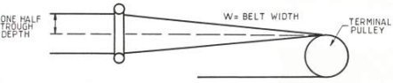
Table 1 indicates the recommended transition distance for half-troughed conveyor applications.
Table 2 indicates the recommended transition distance for full-troughed conveyor applications.
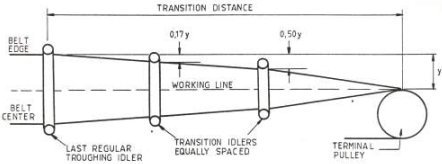
Table 3 indicates the number and location transition idlers.Table 1 - Transition distance for half-trough depth.
TROUGH ANGLE (deg.)
PERCENTAGE OF RATED TENSION
FABRIC BELTS
STEEL CABLE BELTS
20
MORE THAN 90
60 to 90
LESS THAN 600,9w
0,8w
0,6w2,0w
1,6w
1,0w35
MORE THAN 90
60 to 90
LESS THAN 601,6w
1,2w
0,9w3,4w
2,6w
1,8w45
MORE THAN 90
60 to 90
LESS THAN 602,0w
1,6w
1,2w4,0w
3,2w
2,2wNote:-
All conveyors using troughing idlers with angles greater than 20 adjacent to terminal pulleys shall have transition idlers between the given terminal pulley and the nearest standard idler.
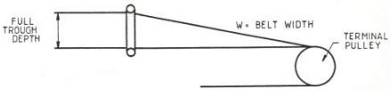
Table 2 - Transition distance for full-trough depth.
TROUGH ANGLE (deg.)
PERCENTAGE OF RATED TENSION
FABRIC BELTS
STEEL CABLE BELTS
20
MORE THAN 90
60 to 90
LESS THAN 601,8w
1,6w
1,2w4,0w
3,2w
2,0w35
MORE THAN 90
60 to 90
LESS THAN 603,2w
2,4w
1,8w6,8w
5,2w
3,6w45
MORE THAN 90
60 to 90
LESS THAN 604,0w
3,2w
2,4w8,0w
6,4w
4,4wNote:-
All conveyors using troughing idlers with angles greater than 20 adjacent to terminal pulleys shall have transition idlers between the given terminal pulley and the nearest standard idler.Table 3 - Number and Location of transition idlers
NUMBER OF TRANSITION IDLERS
FIRST
SECOND
THIRD
FOURTH
1
0,33Y
2
0,17Y
0,50Y
3
0,10Y
0,30Y
0,60Y
4
0,07Y
0,20Y
0,40Y
0,67Y
Stringer Widths
Table indicates standard stringer widths for different belt widths.
BELT WIDTH
(mm)PULLEY FACE
WIDTH
(mm)STRINGER BOLT HOLE
CENTRE DISTANSESSTANDARD
RANGE
(mm)WIDE
RANGE
(mm)300
400
400
500
634
-
450
550
686
-
500
600
736
-
600
700
838
965
750
900
990
1118
900
1050
1144
1270
1050
1200
1296
1422
1200
1350
1448
1575
1350
1500
1600
1727
1500
1700
1752
1880
1650
1850
1904
2030
1800
2000
2058
2184
2100
2300
2362
2489
2400
2600
NOTE: This table agrees with the provisions of SABS 1313-1980 with respect to "standard" range centres only.
"Wide range" centres are not mentioned in this specification.